Introduction:
The reason for me compiling this ‘How To’ guide was simply down to the fact that so many people ask the question, ‘How do I lower my rear beam’. Many answers spell doom and gloom on the job, which isn’t necessarily warranted. Lowering the beam means removal of the torsion bars or, at the very least, removal of one end and the trailing arm repositioned. It is this initial part of removing the arm from the torsion bar that causes so much horror in the minds of the virgin beam re-builder. Yes, the years of exposure to the elements and road dirt will have taken its toll and quite possibly rusted things up good and proper, but the job is still not impossible. It is quite common now to find that the rear outer bearings on the beam have disintegrated once the beam is split, and the job of lowering soon escalates into bearing refurbishment. This happened to me on my first beam and so I decided to write a total refurbishment guide as opposed to the ‘How To Lower’ guides.
This guide is not the authority on how to carry out this procedure; it has just worked for me. It is a job that any enthusiast can accomplish using basic tools and some free floor space. I did all of the 309 beam on an open drive way and in a small utility cupboard! You don’t necessarily need a garage to undertake this task, although it does help considerably.
Tools required:
Tools required are, as said, the basic sort. I have compiled a short list which is obviously non exhaustive but a good start:
- Large flat headed screwdriver (size 8)
- Allen key socket set (size 6 is required for the torsion bar screw)
- Ratchet drive
- Punch set
- Small hammer
- Lump hammer (about 4lb should be the minimum)
- 13 mm combination spanner
- 18mm large ring spanner
- 21mm large ring spanner
- Long breaker bar
- Socket set in above sizes
- Wire brush
- Ford wheel bolt
- File
- Small flat screwdriver or similar implement for scraping rust etc out of recesses
- Penetrating oil
- Large punch driver (I used a 1/4” drive socket extension but be prepared to render it u/s for any further ‘socket’ jobs)
- Drill
- Various HSS drill bits
- Goggles/Glasses for safety
- Earplugs
(The above spanners can obviously be substituted with a socket set but you will probably need deep sockets to fit over the bolt shank. The longer the spanners the better for leverage as some of the bolts will be very corroded and stiff)
Description of parts:
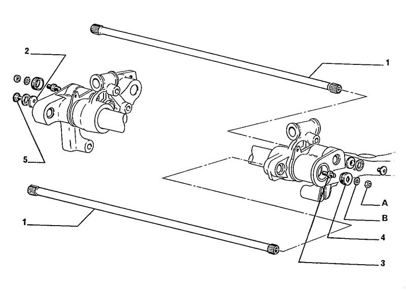
Diagram 1: Rear Torsion Bars
1. Torsion Bar Left and Right
2. Offset washer
3. Cross member screw
4. Hexagonal locking nut
5. Spring washer
6. Plug
7. Torsion bar stud
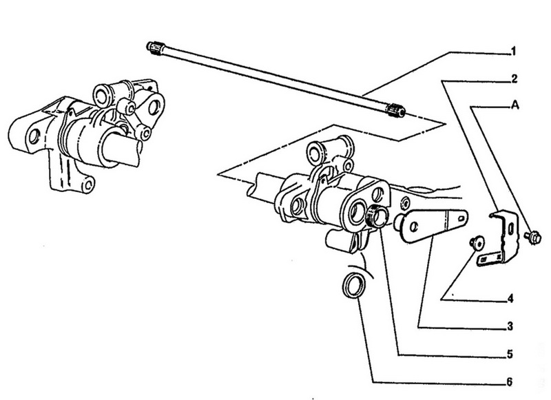
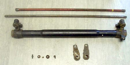
Diagram 2: Rear Anti Roll Bar
1. Rear anti roll bar
2. 13mm Bolt
3. Brake pipe Hanger
4. Plug
5. Bar lever
6. Cross member seal
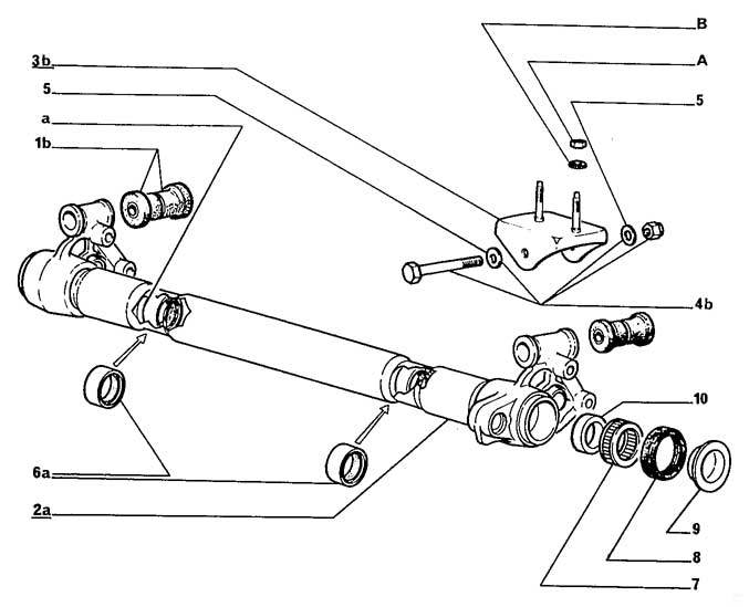
Diagram 3: Rear Cross Member
1. Washer
2. Cross member bracket
3. Hexagonal Nut
4. Washer
5. Mounting bolt and nut
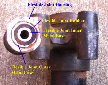
6. Flexible joint
7. Outer bearing
8. Cross member seal
9. Cup
10. Plug
11. Cross tube
12. Inner bearings
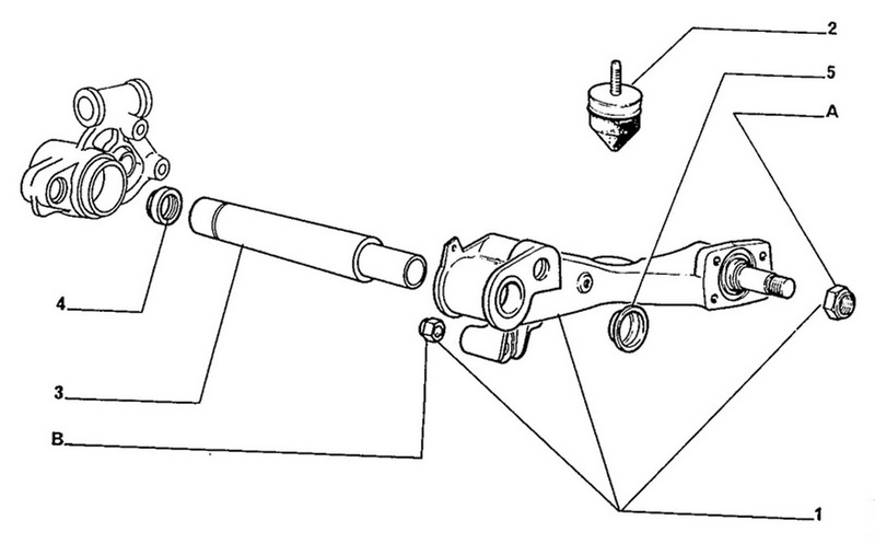
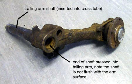
Diagram 4: Rear Arm
1. Trailing arm shaft
2. Trailing arm
Diagram 5: Rear Mounting Flange
1. Nut
2. Washer
3. Rear Flexible Mount
4. Bolt
5. Cross member flange/bracket
Stripping the beam:
Now that the tools have been assembled and the space cleared, the disassembling can commence. Depending on the level of strip the beam is in depends obviously on which step you start on. I have assumed that the beam is off the car and the brakes/discs removed from the trailing arm. The beam can be left on the car but obviously certain parts of it will not be accessible. This is fine if you do not wish to change the front rubber mounting bushes.
First thing is to remove the cross member flange (diagram 5) by undoing the nuts and bolts. These may be very corroded and require some effort to remove. Once these have been removed, access is given to the bolts holding the cross member bracket (diagram 3) to the cross tube assembly. Once removed, the flexible joints are exposed on the cross tube and can be examined. Removal of these flexible joints is covered later. Complete for both sides. The cross member flanges and cross member brackets must be examined for damage around the mounting holes and the welds at the rear mounting rubber platforms. If serviceable, the items must be retained.
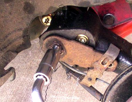
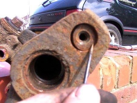
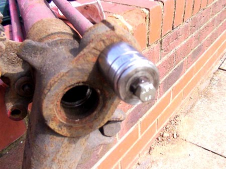
Next is removal of the anti roll bar (diagram 2). The anti roll bar consists of a length of spring steel bar running the length of the cross tube with each end being splined. At each end of the bar, a bar lever is ‘pressed’ onto the splined ends and the lever then bolted onto the trailing arm itself. So, onto the removal. On the outside of the bar lever, in the centre of the cross tube, there is a hole. This hole is threaded but may be full of road dirt, rust, or if undisturbed from the manufactures/refurbishers, a plastic plug. Remove whatever obstruction is in the hole and use plenty of WD40 and/or a sharp implement to clean the threads and the hole. When satisfied this is done, carefully insert a Ford wheel bolt into the hole (M12 x 1.5) It may be necessary to screw in the bolt a little at a time and then remove it completely before squirting some more WD40 or similar onto the threads. This is to help clear out any rust and prevent the threads stripping. The bolt should screw in for about a third of an inch before becoming very stiff to turn. When this is achievable, remove the bolt and liberally smear the threads with grease before re inserting the bolt into the bar lever.
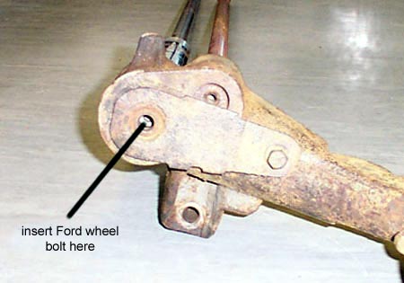
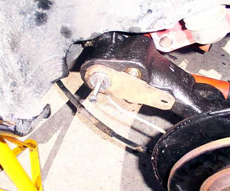
Pic 1: ARB Lever in position and fixed by 13mm bolt
At this point, on the opposite arm, remove the bolt that attaches the bar lever to the trailing arm and loosen the bolt on the arm that you have inserted the Ford bolt into. Going back to the Ford wheel bolt, using a suitable spanner, slowly but firmly, screw the bolt into the bar lever. It is important NOT to strip the threads on the bar lever. However, there is a fine line between the amount of force needed to push the bar out and stripping the threads. You don’t need to lean on the spanner but you do need to use a fair bit of force. Some common sense given the size of the bolt should be exercised here. The bar lever should begin to force itself off the anti roll bar splines. The bolt should stiffen significantly at first and then free up slightly as the bar begins to slide from the bar lever. Turn the bolt for a few turns checking the lever arm for movement. If it seems to be remaining still, check the other side for movement. Only one lever will pull off at a time but it is uncertain which one it will be first. Constant checking should be carried out. When you can ascertain which arm is moving, the 13mm bolt holding it still to the trailing arm can be completely removed with the opposite sides bolt staying in place (to prevent the lever rotating when you tighten the Ford bolt). Continue until the lever arm is fully removed. The rubber seal used on these arms is a good fit in the tube and can make the remaining arm difficult to pull out. Use a screwdriver or similar to prize it out.
Pic 2: Winding in the Ford wheel bolt into the ARB lever arm
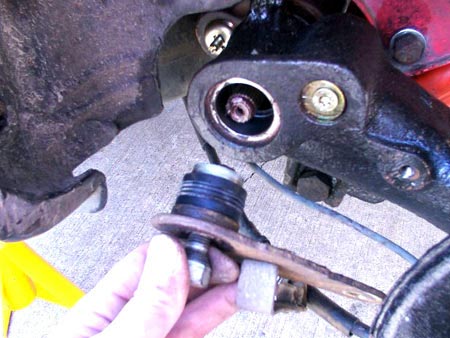
Pic 3: ARB Lever arm removed revealing splined end to ARB
Pic 4: ARB Lever with 13mm bolt removed and lever twisted up
Now, working on the opposite arm, replace the bolt attaching the bar lever to the arm that you took out previously. Repeat the above procedure removing the bar lever from the bar and then withdrawing the anti roll bar from the cross tube.
It must be noted that the bar has different thickness splined ends. The right hand bar lever has three notches on the inside face around the splined hole. This will only fit on one end of the bar and therefore the bar should be re assembled later in the same configuration. It should also be noted that as long as one bar lever is removed, the anti roll bar can be withdrawn from the cross tube without having to remove the other arb lever. This can remain in place until reassembly if required.
At this point, you may think that the job is easy and you ever wondered what the problem in starting it was.
Alternatively, you may be experiencing problems with getting the bar levers off. I can only suggest that you try removing the bar levers a bit at a time alternating from each end. One end may be freer than the other. As long as one lever can be successfully removed, the job can continue. Should you strip both bar lever threads, then the job becomes a whole lot more complicated (but not impossible just yet!).
Assuming that the anti roll bar has been successfully removed, the torsion bars can be tackled next. There is some prep to be done before removal though.
I shall start with the removal of the suspension bar washer (diagram 1), which is an offset hole type washer. Once again, years of road grime and dirt will have accumulated in the recess. Pick an end of the beam and locate the end of a torsion bar on the trailing arm itself. You will see a recess with a small allen key or hex drive bolt in it.
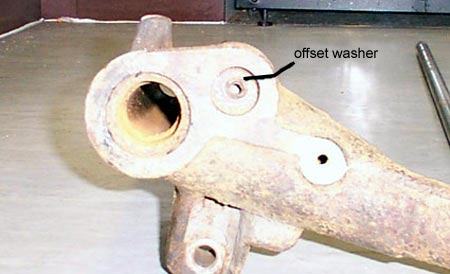
Pic 5: Trailing arm showing offset washer with screw removed
If the bolt looks rusted, use a sharp screwdriver and hammer to gently chisel around the bolt head where it butts against the washer surface. Next, insert an allen key or hex socket into the bolthole and sharply tap the end with a hammer as if you were trying to nail the bolt into place. This shock treatment will hopefully loosen up the bolt sufficiently to prevent the allen key recess from stripping. Crack the bolt free using a socket drive and remove the bolt.
Using a screwdriver or similar, scratch and chisel away all the rust and road dirt from around the recess and washer. There is a slot into which the washer must move before it can be withdrawn from the recess. This slot must be totally cleared of dirt as far around the recess as possible bearing in mind the washer occupies some of the slot. When this has been done to your satisfaction, use a pin punch and hammer to ‘slide’ the washer towards the slot you previously cleared out. When the washer begins to move you will see how it works. Centre the washer and remove from the recess. The end of the torsion bar is now exposed. On the same torsion bar but now at the opposite end, you will see a threaded stud with a screw slot in the end (suspension bar stud). There will also be a lock nut on this stud and maybe a spring washer. Remove this lock nut and washer.
Using the largest flat-headed screwdriver you have, gently attempt to screw the stud in to the bar (weird I know but trust me on this for a minute). If this is a definite no go then attempt to unscrew the stud. Be careful not to break the stud slot. If you do then all is not lost as a new slot can be cut into the end using a hacksaw and off you go again.
Pic 6: Scraping away the rust from the offset washer recess
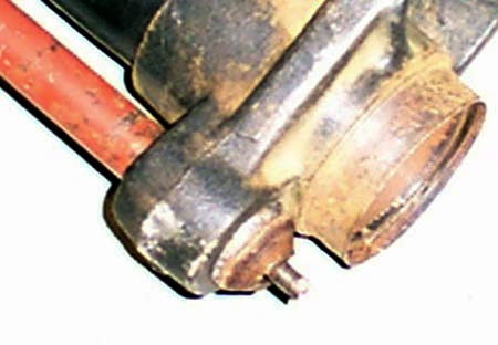
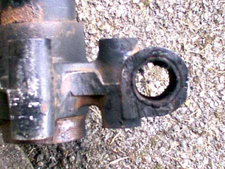
Pic 7: Torsion bar stud and cap in cross tube mount
(Note: cap is deformed in this picture)
If the stud does turn, it will only do so for a few turns either way before going stiff again. At this stage, do not try and force the stud to turn any further.
Repeat the above procedure for the opposite arm.
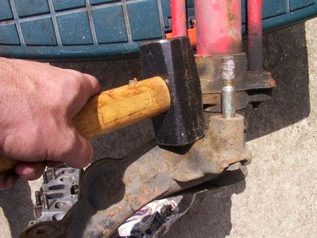
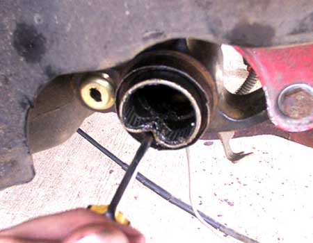
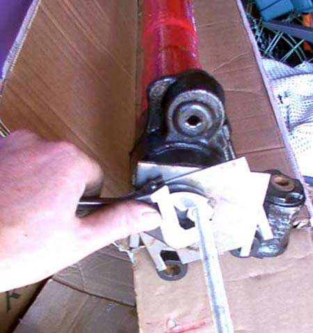
Once the above has been completed, this is all that can be done to prevent the torsion bars being held in the trailing arms and cross tube. In theory, the arms should simply pull out of the cross tube. It may be worth while gently tapping the inside of one of the trailing arms to try and persuade the arm shaft out of the cross tube. It is very unlikely, although not impossible, that the arm will come away from the cross tube and therefore one end of the torsion bar withdrawing from its mounting hole. A puller system can be improvised to encourage the bars to shift as shown in the picture. Ensure the socket uses is large enough to clear the end of the torsion bar and that the 8mm bolt is wound fully into the end of the bar before the nut is attempted to be undone, thus pulling the torsion bar from its fixing.
Pic 8: Socket, bolt, nut and washers make up a simple puller
What is more likely is that the torsion bar splined ends will be well and truly seized in the mounting hole at either or both ends. Some way of supporting the beam assembly and at the same time, hooking one end of it over a non-moveable object must be found. This will now enable the inside surface of the trailing arm to be struck with a large lump hammer. Some force will be required depending on the severity of the seizure. It is advisable that ear and eye protection be used during this ‘persuasion’. It may appear to be a very harsh method of treating a rear beam but it is usually the only way the arms can be separated.
After several well aimed blows, it should be evident that the arm is withdrawing from the cross tube by the gap between the cross tube and arm increasing at its pivot point. You should also be able to see which end of the torsion bar is pulling out. Hopefully it will be the end that is mounted on the cross tube as this will be cheaper and easier to release the other end of the bar later on.
If not, it does not matter too much. My torsion bars remained stuck in the cross tube hole with the arm separating from the bar. I could not hammer the torsion bar stud to force the bar out as it would have simply distorted. The only way was to hammer the trailing arm end of the bar and force the bar through the cap and out. The cap and shouldered stud are replaceable.
Keep going until the arm is fully withdrawn from the cross tube. Repeat the process for the opposite arm.
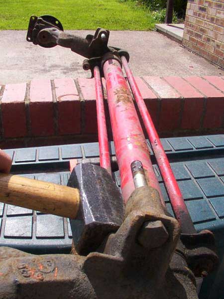
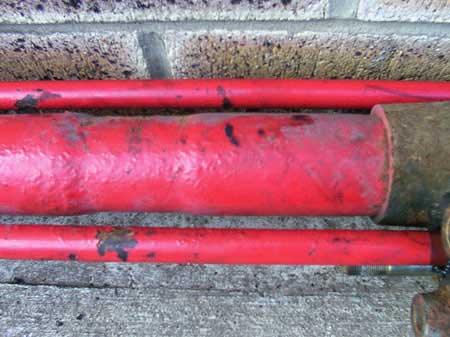
Pic 9: One end hooked over the wall
The opposite trailing arm is hit with a hammer
Pic 10: Strike the arm here or where the torsion bar enters the splined hole
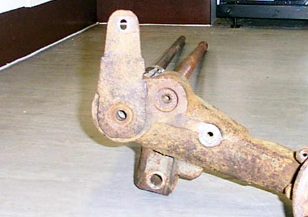
Pic 11: Trailing arm assembly (Passengers side)
Don’t worry about the state of the trailing arm shafts at this point despite it looking bad, our main concern is to fully remove the torsion bar. Note that each bar is ‘handed’. This means that the bar controlling the left hand trailing arm and the right hand trailing arm must be replaced in the same position. The bars were originally marked with yellow bands.
The right hand trailing arm is identified with one painted ring where as the left hand one is marked with two rings. If the rings are not evident, mark them up yourself before removal.
Whichever end of the torsion bar is still attached, from the other end, bash the bar out through the hole. As mentioned, it may require the suspension bar stud being forced out through the cap on the end. Again, this looks harsh but all the pieces can be replaced for not much money. The only damage that can be a worry is the deformation of the screw holes in the end of the torsion bars themselves. Some sort of protection should be used where possible in the form of a scrap piece of metal. I have had to reclaim the threads on my bars before using a tap and die set but this can be difficult. As long as some consideration is given to not damaging the ends then the threads can be reclaimed. You may have to add this to a list for the friendly garage to do.
Both torsion bars should now be separated from the beam along with the anti roll bar and the trailing arms.
Most of the parts will now be separated. The cleaning process can now begin. There is little point in spending too much time in cleaning up the arm shafts as these will most likely be beyond repair and should be replaced. Pay more attention to the beam itself. Clean off as much of the road dirt and rust as possible using wire brushes etc. This will reveal any other damage that may be lurking, it also means you won’t get filthy every time you handle the parts.

Pic 12: Some of the rear beam components
I started with the easy bits like the torsion bar and anti roll bar splines. Using a wire brush along the line of the splines, get the worst of the corrosion off. Next, using a sharp edge thin enough to go between the splines, scrape any more corrosion off. Repeat this for the whole splined end. It pays to take time on this so that the bars, when greased, will slip easily into and out of the trailing arm and cross tube.
Both torsion bars and the anti roll bar need to be subjected to this treatment. When you are satisfied that the splines are as clean as you can get them, lightly oil the bare metal surfaces and store in a dry place.
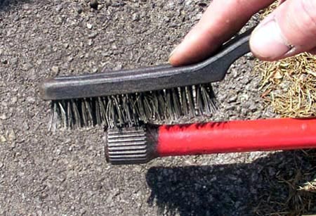
Pic 13: Wire Brush Treatment
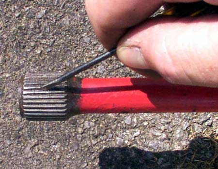
Pic 14: Scraping the rust from the splines with a sharp point
The splined hole in the trailing arm and cross tube also need to be cleaned of rust. That sharp point will come in handy again. If possible, small wire brushes can be purchases that with a bit of modding (made slightly thinner) will move through the hole.
Now that the offset washer has been removed, the recess can be seen more clearly. This needs to be thoroughly cleaned of dirt and the recess in which the washer sits dug out so that the washer can freely move around. In general, the more corrosion/dirt that can be removed the better, especially if the parts are to be painted. There are some paints such as Hammerite that can be painted directly onto rust but it’s best to get the worst of it off.
Removal of the cross tube bearings is next on the list. The outer bearings will almost certainly need replacing, the inner bearings may not be so bad. Inspection of the trailing arm shaft will make the decision for us.
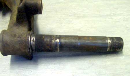
Pic 15: A Knackered trailing arm shaft
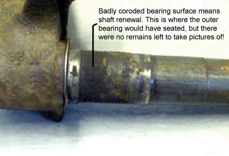
Pic 16: Trailing arm shaft outer bearing damage
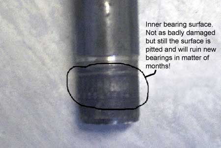
Pic 17: Trailing arm shaft inner bearing surface
As can be seen from the above pictures, the shafts are pretty knackered at both ends. The shafts will definitely be replaced and in this case, I chose to replace both inner and outer bearing races in the cross tube, the process of which, is covered later.
Before we can get to the outer bearing race, the suspension arm seal needs to be prized out from the end of the cross tube using a flat head screw driver. This will reveal the outer bearing face.
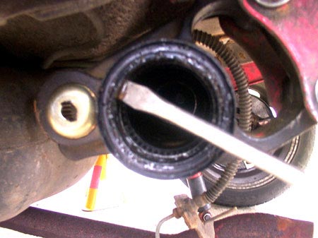
Pic 18: Prizing Out The Suspension Arm Seal
Removal of the outer bearing race is relatively straightforward. No special tools are required except from a thin flat head screw driver and a hammer. Some care will need to be exercised in order not to gouge the cross tube itself where the bearing race sits. On inspection of the cross tube end (where the shaft goes in), you should be able to see what remains of the outer bearing. The flat head of the screwdriver needs to be inserted between the bearing casing and the cross tube. Gently at first, tap the screwdriver in a little way and then remove it. Move around a little and repeat this process. With continual tapping and moving around with the force used increasing, the bearing race will begin to deform and eventually fall out.
Pic 19: Prizing Out The Outer Bearing Race
The cross tube now needs to be inspected for damage that may have occurred due to over zealous hammering/chiselling. Don’t worry too much as small gouges can be sanded out using wet and dry paper. The surface needs to be smooth to the touch though in order that the new bearings can be seated properly.
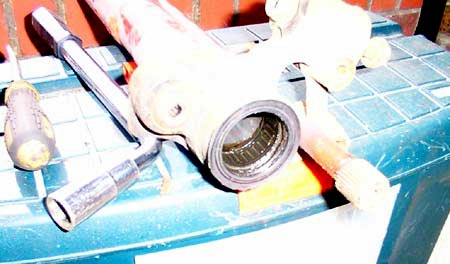
Next the inner bearings can be tackled. A Peugeot Dealer can undertake this task if you are unable to source the materials to build a puller or a length of tube to knock the bearings out from the opposite end of the tube. The bearings are smaller in diameter to the outer bearing and initially fall into the cross tube with little resistance. You can see from the cross section of the tube, that it narrows before widening again in the centre. It is in this narrow section that the bearing is pressed. Using a ruler, measure the distance from the end of the cross tube to the bearing edge and make a note of this. It should be around 20cm. The new bearings need to be pressed into the tube to the same distance give or take a cm but no more. This can be achieved using an old (or new if you are careful) shaft inverted so that it enters the cross tube ‘fat end’ first. Use a lump hammer to knock the bearing down the cross tube to the required depth. From the following picture, the wasted section of the cross tube can just about be seen. It is in this section that the inner bearing has an interference fit and needs to be seated.
Pic 20: Cross Tube Wasted Section
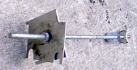
Peugeot have a special tool in order to ‘pull’ the bearing from the tube. It can easily be made up using readily available materials and basic tools. As long as the dimensions are correct the finish need not be that good, it all depends on how much time you want to spend on it. Pictures on how this tool looks are at the end of this guide.
Using the puller, the inner bearings are persuaded out. It may be necessary to release the tension applied and rotate the tool 90 degrees before trying again. Eventually the bearing will pull out of the shaft. I have read of alternative methods using a bar inserted from the other end of the tube knocking the bearing out that way. Another, simpler method is to use a length of rod ground down to a spike at one end. Use this in a similar way to extracting the outer bearing. Wedge the spike using a hammer, between the cross tube wall and the bearing race. Eventually the bearing race will deform and the debris removed. Problems with the last method are creating gouges in the cross tube wall causing the inner bearing to deform slightly when re-seated. This can cause stiff operation of the trailing arm and possibly premature failure.
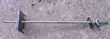
Pic 21a: Inner Bearing Puller
Pic 21b: Inner Bearing Puller
Pic 22: Bearing Puller In Use
When both bearings from both ends of the cross tube have been removed, the tube can be cleaned of waste bearing material and or rust that may have accumulated. Internal cleaning of the whole cross tube only needs doing thoroughly if grease nipples are to be applied to the tube later to prevent the fresh grease becoming contaminated. At the very least, the point where the inner bearing is seated needs to be as clean as possible.
Before fitting the new bearing, they must first be packed with good quality grease. It is important to do the inner bearing, as access to it once it has been pressed in will be limited. I did not have access to a suitable press and therefore improvised when it came to fitting the inner bearing. I used an old trailing arm shaft. Firstly, having greased the inner bearing, insert it into the cross tube ensuring the stamped markings on the bearings outer race are facing you. The bearing should, when released, fall down the tube until it meets the wasted section where it will stop. Then insert the old trailing arm shaft so that the thick end goes into the tube first. Be careful at this point to ensure the bearing is level and ready to be driven into position. Using a lump hammer, strike the other end of the shaft until the bearing has been driven into the wasted portion of the cross tube to a depth of around 20cm.
For the outer bearing, I used a plastic mallet to initially seat the bearing, again with the stamping marks facing outwards, into the end of the cross tube. I then used a piece of wood and a hammer to drive the bearing home so that it was recessed into the tube by around 5mm. This allows the cross tube seal and the trailing arm shaft cup to seat without fowling the bearing race. A large socket of the correct size or length of tube would be more suited to this job if they are available.
Fitting the new cross tube seal is a simple case of greasing the inner lip (you should be able to see a silver band recessed into the lips), and then hammering it home using a piece of wood as protection. Extra grease around the bearing race and seal should help prevent the ingress of dirt and moisture.
Pic 23: Cross tube end showing outer bearing race and outer seal
The trailing arm shafts should now have been replaced. These items need to be pressed in and out. Hopefully a local garage will do this for you or let you use their press. The job takes about twenty minutes to remove and replace both shafts so don’t be fobbed off with a huge bill. Only once have I had to run a ring of weld on the inside of the trailing arm shaft at the point where it is pressed into the arm. This helped contract the shaft inwards slightly allowing the press to do its job. The arm was very badly corroded onto the shaft in that case.
Press the new shafts out taking note of how far they are recessed on the trailing arm. Some are flush with the outer face of the arm; some are recessed by around 5mm. Once the new shafts are pressed in, the new bearing cups (item 9 on diagram 3) can be knocked into place.
Now it’s time to move onto the forward flexible joints if these are to be replaced.
Flexible Joint Replacement - Method 1
This is one of the more time consuming processes, as it requires some delicate cutting with a hacksaw. The flexible joints may or may not require replacement. They are extremely hard wearing due to the relatively small movement they are subjected to. It is important that you use good quality hacksaw handles (blades are blades!). You will require at least a junior hacksaw but it is better if you also have a standard size saw as well.
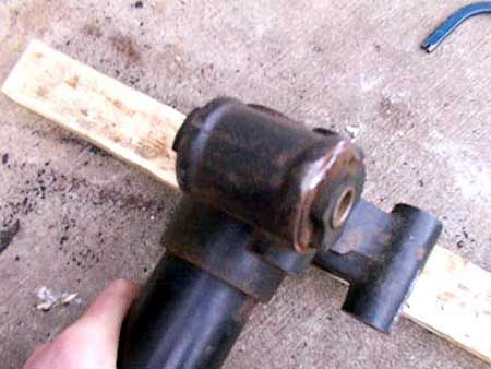
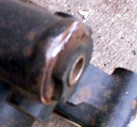
Each side of the rear beam uses two flexible joint bushes, one being pressed in on each side of the mounting hole. The have a lip on them preventing the bush from being pressed in too far. It is this lip that prevents the bushes simply being ‘pressed’ out.
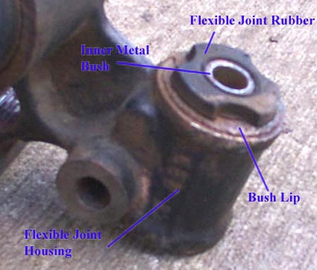
Pic 24: Rear Flexible Joint
Firstly, the lip has to be sawn off. Care must be taken to prevent too much damage being caused on the mounting web itself. Keep the saw at the correct angle and take it slow. The lip is barely thicker than the saw blade itself. Saw off a small amount of the lip until it resembles the pictures below.
Pic 25: Using a Hacksaw To Cut Off The Bush Lip
Pic 26: Bush Lip Partially Sawn Through
Pic 27: A Close Up Of Above
Once the lip has been partially cut away, it should be possible to use a sharp flat head screwdriver or chisel and hammer to lift the lip away from the beam. You won’t be able to remove the bush this way but it does make sawing the rest of the lip off that much easier. It also prevents a lot of damage from occurring to the beam itself.
Pic 28: Screwdriver Used To Lift Lip From Beam
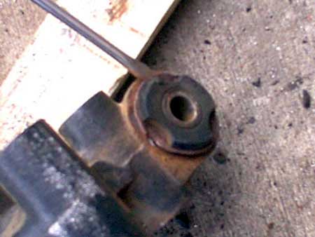
Once that has been done, you should have something looking like this:
Pic 29: Flexible Joint With Lip Removed
The same must be done for the second bush at the same end of the beam. Note that in the above picture, it looks like I have cut through the whole housing due to the nice shiny metal showing. This is NOT the case. It is shiny, as the blade has removed the top layer of rust. Only the thickness of the lip and protruding rubber from the bush was removed.
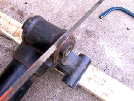
Now the junior hacksaw is needed as the blade needs to be put through the inner metal bush and then reassembled to the saw handle. The idea here is that a small portion of the inner bush and Rubber can be cut away exposing the bushes outer metal case. The rubber has a tendency to clog the teeth on the saw making progress very difficult. Concentrate on cutting the metal of the inner bush only for now. When one slot is cut, move the saw blade about 90 degrees (ish) and cut again down to the rubber. You will have to now use a parallel punch, screwdriver etc, to gouge, knocks the small metal section out. It’s quite awkward as the rubber is bonded to the inner bush very firmly but it will eventually come out. With this metal slither removed, get the larger saw blade in there and hack away at the rubber so that it disintegrates leaving a nice clear wedge shape. Note, the picture below may look like I have cut through the flexible joint housing (due to the line on the top). This is NOT the case; it is merely a casting line with the rust highlighting it.
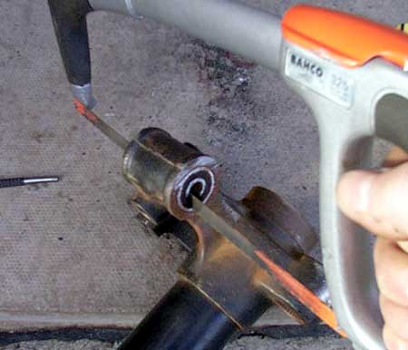
Pic 30: Hacksaw Through The Rubber
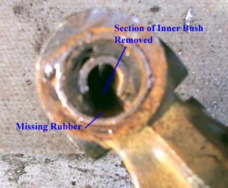
Pic 31: Wedge Cut From Inner Bush and Rubber
Now, with the hacksaw still fed through the bush, the outer casing must be cut through. Great care must be taken not to cut too deeply into the flexible joint housing. Take it easy and don’t press too hard with the saw, let it do the work. When the casing has been cut through, the bushes can now attempt to be removed. A parallel punch can be used with a hammer to slowly punch around the outer casing. It will distort and bend into the middle and some force will be necessary to get the bushes moving. After a while the bushes should pop out leaving the housing relatively intact.
The Bushes however, will not be salvageable! A clean up with some emery paper or fine file on the surfaces of the housing is all that is needed in preparation for the new bushes.
The new bushes have a small half moon section cut out of the lip. This cut out must be in the vertical plane (12 o’clock or 6 o’clock position) when inserted into the housing. This is so that the Y shaped rubber can act against the forces of the beam during cornering adequately.
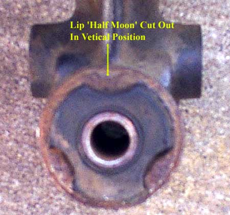
Pic 32: Flexible Joint Half Moon Cut-out
To insert the new bushes, a large socket can be placed over the protruding rubber and the bush knocked in. Care must be taken not to deform the lip. I got the bush lined up with gentle taps from a hammer and then used a lump hammer to knock them in as they were just as hard to get in as out. Hopefully though, it will be the last time they will ever need to be removed.
Flexible Joint Replacement - Method 2
This method uses a blowtorch to burn out the rubber bushes leaving the metallic sleeve in place in. Ensure you have an open area before doing this, as the smoke given off is quite thick and toxic. It also looks quite drastic as well but don’t be put off. Follow method 1 to the point where you cut off the bush lip carefully with a hacksaw. Again, you will need to do both sides of both ends. Now, using a standard blowtorch with plenty of gas left, concentrate the heat on the rubber parts of the bush. After a minute of so, the rubber will begin to burn. Continue burning simultaneously poking it around with and old screwdriver or similar. Eventually the central metal tube will melt its way out. When both sides are done and most of the rubber is removed or burnt away, the flame can be extinguished and the remains left to cool.
Now using a hacksaw carefully cut along the length of the remaining bush sleeve as you would in method 1. This time though, it is much easier to see how deep you are cutting. Once done, using a combination of parallel punches and sharp pointed implements, bash out the bush sleeve.
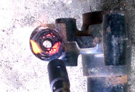
Pic 33: Burning out of bush rubber with blow torch
Pic 34: Leaving only the outer metal bush casing
Method 2 is, in my opinion, the quickest and easiest method of removing bushes. It makes cutting the outer bush case more accurate thus preventing cutting into the cross tube mount itself. Clean the hole out with some fine emery cloth to clean up the rust. Lightly grease the internal surface and offer up the bush to the hole. Using a piece of wood over the bush and a lump hammer, Hammer the bush into the arm using three or four heavy blows until the lip of the bush is flush with the tube mount.
It should be noted that the above two methods are also suitable for the removal and replacement of the front wishbone bushes on GTi models.
On my beam I have opted to fit the solid mounting kit available from Peugeot Sport. The kit substitutes the flexible joint for a solid nylon block, machined to the same shape and inserted in the same way. This kit, although listed for the 205 model, will fit the 309GTi beam. The front nylon blocks simply hammer in and the rear aluminium blocks will align to the 205 mounting points on the car. I had to lever the entire cross tube mounting flange over by no more than 10mm until the bolt threads went through the hole and I was able to fix a nut on to it. The beam or its mounts are not deformed in any way. Vibration is not as bad as I thought it would be but the ride is slightly harsher. The rear end through corners though, is very tight and controllable.
Here is a picture of the kit I purchased:
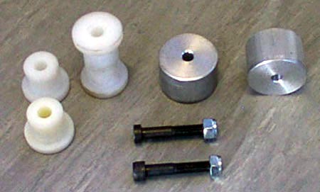
Pic 35: Rear Axle Solid Mount Kit
If anyone has access to a lathe and the raw materials (Nylon rod and aluminium), then this kit can be made very easily and very cheaply. Much less than the cost from Peugeot anyway.
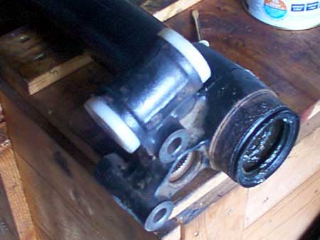
Pic 36: Nylon solid bushes fitted to front mounts of cross tube
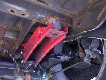
Pic 37: Rear crossbeam mounts now an aluminium block
Re-assembling the beam: The cross tube bearings, seals and mounting bushes are now replaced. The trailing arm shafts have been renewed and the splined ends of the torsion bars and anti roll bar have been cleaned up. The only thing left to do is reassemble the beam.
Where you do this is up to you, either on the car or off it. First of all, you must decide on a ride height for you car. The height is ‘set’ by adjusting the height between the centres of the mounting points for the shock absorbers. I opted to set the height with the beam on the car. Peugeot state that the distance between shock mounting points should be:
- Models with engines XV, XW and XY7: 340.0mm
- Models with engines XY8: 336.0mm
- Models with engines XU5J and XU9J: 330.5mm
A change in the dimension between shock mounting bolt centres of 2.0mm is equivalent to a change in ride height of 3.0mm.
I used the above figures as a guide and decided to set the shock centres to 305mm. This was done on the car using a jack under the trailing arm to lower/raise it and a tape measure to get the correct distance. Once the distance was set, it is a case of trying to slide the torsion bar relating to the trailing arm you’re adjusting until it slides into both the arm and the cross tube, first ensuring that the torsion bar stud is fitted to the correct end of the bar. I did this from under the car. It may take several attempts but by rotating the bar one spline at a time and trying again, eventually the bars splines will mate and slot in easily. Now do the other side in exactly the same way. It is very important that the height is the same on both sides. Ensure the splines are fully engaged at both ends of the bar and then refit the road wheels. Using an old bolt or similar, tap the end of the torsion bar (offset washer end) until is fully seated in its spline, flush with the inner lip of the offset washers groove. From under the car, check that the trailing arms are fully seated in the cross tube and haven’t been pushed out by the insertion of the torsion bar.
Remove the axle stands and lower the car down. Ensure the underside is clear of jacks and tools and then bounce the car to allow the suspension to settle. View the car from the side to see if the ride height matches your requirements. Jack the car up and replace the axle stands. If the height needs adjusting, use the jack to take the weight of the arm and remove the shaft, reset the height of the arm and reinsert the bars as described. Two or three attempts may be necessary until the final height is found. I decreased the distance between shock bolt centres to 305mm. This gave me the ride height as shown. It must be noted though, that the 309 beam uses stiffer torsion bars which will not sag as much under the cars static weight. Lowering the 205 beam to the same dimensions may give a lower stance that shown.
Pic 38: Ride height
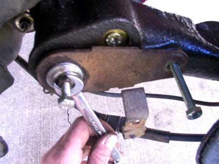
With the bars fully home in their splined hole, fit the offset washer and rotate it until the screw can be inserted. Tighten the screw up and at the same time, wobble the trailing arm up and down to take the weight off the torsion bar. When tight, move to the opposite end where the screw stud is. Wind the stud all the way in until it stops but do not over tighten it. Fit the nut and then tighten it so that it pulls the stud and bar. If the stud rotates, use a screwdriver to hold it in place. It will get quite tight and you should be able to see the bar move very slightly. Now release the nut until it becomes loose. Check the relative trailing arm for any gap between it and the cross tube. There shouldn’t really be any gap, as the seal will butt up against the arm. Go back to the stud and wind it out slowly until you feel it butt up against the outer cup. Stop at this point and hold it in place with the screwdriver. Now tighten up the nut so it tightens the stud preventing it from turning. Do the same for the other torsion bar.
Pic 39: Torsion Bar Stud Tightening
Now the anti roll bar can be fitted.
If one of the anti roll bar lever arms has been left on the end of the bar itself, simply insert the bar through the crosstube and align the hole in the lever to the hole in the trailing arm. Insert an 8mm bolt to prevent the lever from twisting. On the opposite end of the anti roll bar, use a long bolt to align the lever plate. Using a similar bolt, pass it through the end of the lever arm where the Ford wheel bolt went to remove the lever With a bit of jiggling, the bolt should screw into the end of the anti roll bar and help align the splines of the bar with the mating splines of the lever. Using a simple puller set up as shown in the picture, the lever can now be tightly secured onto the bar itself.
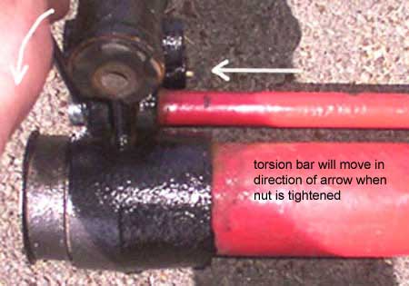
Pic 40: Puller system to re seat anti roll bar lever
Pic 41: Winding in the nut to push the lever onto the ARB
Note in the above picture the use of a long bolt on the right hand side. This prevents the anti roll bar lever moving whilst the lever is pressed onto the bar. The bolt is removed when the procedure is complete.
Sometimes, the ends of the anti roll bar get damaged when the Ford bolt was used to wind the lever arm off. The threads can get damaged causing problems with winding the arms back on using the above method. In this case, the lever arms can be hammered into place. Use the long 8mm bolt to align the splines and get a helper to hold a mallet against the opposite bar end or fitted lever arm. This acts like a reaction block allowing you to hammer the opposite lever arm on. It may take a few attempts but it can be done. When the lever arms are fully seated on the anti roll bar, the bolts can be replaced with the correct length items and screwed in tight. Remember to fix the handbrake and brake pipe mounting bracket as well at this stage.
The job is near completion. Refitting the shocks may require you to remove the axle stands (wheels fitted of course) and lower the car slightly so the weight of the car compresses the suspension. The shock length will be too small otherwise to reach the mounting holes. With the shocks fitted, securely tighten the mounting nuts. Check all nuts and bolts for tightness at this stage.
It is worthwhile, having driven a few miles, to jack the rear end up again and support on stands. Check all nuts and bolts for tightness. Also check that the trailing arms are still seated correctly in the cross tube and that the offset washer screw and torsion bar stud and nut are tight.