Jump to content
  • Welcome to 205GTIDrivers.com!

    Hello dear visitor! Feel free to browse but we invite you to register completely free of charge in order to enjoy the full functionality of the website.

mrfirepro

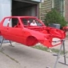
[Car_Restoration] My 1989 205 1.9 Gti Restoration Project

Recommended Posts

mrfirepro

Overall the project has stalled a little as the shell is progressing well, but a bit slow. I'm now not getting it back for another 4 weeks.


Having had time to reflect on the whole dipping process I am very pleased with the results and only having to do 4 small bits of welding has been a real bonus. However on the financial side I am not convinced it's worth the extra money for a bit more peace of mind. In deciding to dip the car I was hoping that the resultant body work costs would be less, as there would be no mechanical strip, however the costs of replacing all the seam sealer has been at least equal to any stripping costs. Anyway here is the shell with nearly all the seam sealer replaced.


P1030527_666x500.jpg


We also finally decided to deal with the crushed floor pan (I know there not jacking points :lol: ) by cutting out the internal floor and knocking the external skin into shape and re-welding the internal floor, here is the finished article.


P1030530_375x500.jpg


Here is the finished engine and gearbox now fully assembled (still a few bolts needed for the eagle eyed) and almost ready to go.


P1030591_666x500.jpg


Thanks to Farmer who managed to find me a new oil cooler body and countless other items.


I'm now starting to get on with refurbishing the seats, runners and external trim so bought myself extra stanley blades and a large box of plasters.


I have also been pondering the correct re-assembly process (when I get the shell back) as I want to avoid removing already fitted items and making it as easy as possible, here are my thoughts (any comments advice would be well received)


1. Fit rear beam

2. Fit front subframe

3. Fit fuel and brake lines

4. Fit fuel tank

5. Fit all rear of engine bay items including looms

6. Fit engine/bearbox

7. Fit drive shafts

8. Fit front struts

9. Fit internal loom/dash

Edited by mrfirepro

Share this post


Link to post
Share on other sites
RossD

Very very nice! Also just noticed that you must be just up the road from me, both being in Maidstone! (I'm in Loose)

Share this post


Link to post
Share on other sites
mrfirepro

I'm in Collier Street, about 5 miles from you. Nice to know there are others local, if ever your passing or need a hand feel free to contact me.

Share this post


Link to post
Share on other sites
Tom Fenton

I would alter your list to as per below. Fuel and brake lines definitely first. Then tank, then beam.


3. Fit fuel and brake lines

4. Fit fuel tank

1. Fit rear beam

5. Fit all rear of engine bay items including looms

2. Fit front subframe

6. Fit engine/gearbox

7. Fit drive shafts

8. Fit front struts

9. Fit internal loom/dash

  • Like 1

Share this post


Link to post
Share on other sites
RossD

I'm in Collier Street, about 5 miles from you. Nice to know there are others local, if ever your passing or need a hand feel free to contact me.


Excellent - And vice cersa - If you need a hand just give me a PM!

Share this post


Link to post
Share on other sites
welshpug

Tom is spot on, its a right faff trying to get the fluid lines up over the tank and down the side of it, do it with the tank off and its a doddle.

  • Like 1

Share this post


Link to post
Share on other sites
mrfirepro

Tom/Mei, thanks for the advice, I'm really glad I asked.


Ross - what are you doing for the next 25 weekends :D , well you did offer......


On another note, I have been thinking about the brake lines and reading lots of threads on here., but one thing is clear, some people manage to make there lines look beautiful and some people...well...don't.


I cant seem to get to the bottom of what is done to make them look so neat and tidy (and straight), I'm probably going to order the copper/nickel pipes & fittings sometime this week.


If there is some knack or special tools I would really like to know.

Share this post


Link to post
Share on other sites
Tom Fenton

All I do I straighten the pipe first of all using some angle iron in the vice. Trying to straighten it off the reel by hand gives at best a wavy line. From straight it's then easy enough to bend it to shape using a small pipe bender to get nice even bends. It's a satisfying job but I have to be in the mood to do it!

Share this post


Link to post
Share on other sites
RossD

Ross - what are you doing for the next 25 weekends :D , well you did offer......


Haha! I'm busy until after Easter at the moment (Getting mine back on the road on Sat) but could probably spare an hour or two to help after that.


I dropped the tank like others have said. Also gives you the chance to check for any corrosion and give it a good clean and rustproof under there. 2 bolts and the jubilee clip holding the filler pipes on and you can swivel it out of the way.


As for making them look nice, one trick is to cut the pipe to the correct length, or just over. Place it on a flat surface and get a big heavy hard back book and roll the pipe between the book and flat surface until you have a nice smooth length of pipe free of wiggles, kinks and random changes of direction. You can then fit it, making the bends as gently as possible and using formers like sockets for the tighter bends.

Edited by RossD

Share this post


Link to post
Share on other sites
mrfirepro

Thanks Ross,


Sounds like a good idea, was also thinking about a straightener used for MICC cable, I think we'll have some of these at work and was going to give them ago.


So hopefully one way or another I'll get some straight pipe. Going to pick the shell up on 17th, so will be doing this over the Easter weekend

Share this post


Link to post
Share on other sites
mrfirepro

Just started to refurb my steering wheel, which is the first time I have tried any trimming so will let you know how I get on.


Now my engine has been rebuilt with all ancillaries and GB, I was thinking about filling it with oil and turning it over on the starter motor to get the oil circulated as it may be some considerable time before the engine gets installed and is fired up, but I have a few questions.


1. is this advisable or not, is there anything else I should think about?

2. If so if I just connect a battery to the starter motor to get it to turn over I wont be doing any damage?


Thanks

Edited by mrfirepro

Share this post


Link to post
Share on other sites
Tom Fenton

Personally I wouldn't bother. Pull the plugs out give it a good dose of duck oil or similar down each bore then put the plugs back and leave it alone. I take it you have used graphogen or some other build assembly lubrication on the bearing shells and cam bearing journals and followers?

Share this post


Link to post
Share on other sites
mrfirepro

Personally I wouldn't bother. Pull the plugs out give it a good dose of duck oil or similar down each bore then put the plugs back and leave it alone. I take it you have used graphogen or some other build assembly lubrication on the bearing shells and cam bearing journals and followers?

No :( just generous amounts of clean engine oil, is this a problem???

Share this post


Link to post
Share on other sites
Tom Fenton

Trouble is engine oil will just drain away in a matter of a day or so, Graphogen or similar stays there until the engine is fired up and gets hot.

Do not worry about it, I would not go disturbing the bottom end, but it would be worthwhile for me to pull the cam cover and then the cam caps one at a time, and give the cam bearing journals and lobes a smear of something.

For the bottom end, when you do come to start it, take the plugs out, again some oil down bores for the rings, then spin the engine over on the starter until you 100% have oil pressure up on the gauge. If you don't trust the standard Peugeot dash gauge (I don't) then get a seperate mechanical pressure gauge on there to make sure 100%.

Share this post


Link to post
Share on other sites
mrfirepro

Thanks Tom,


Where is the best place to put the gauge and what sort of pressure am I expected to see as normal?

Share this post


Link to post
Share on other sites
Tom Fenton

Easiest way is to remove the standard pressure light switch (smaller of the two) next to alternator then get a gauge fitting that goes there (16x1.5 thread from memory). On a newly built engine I have seen upo to 60psi oil pressure whilst cranking but to be honest anything around 20psi is OK. When you first start cranking you will see little or nothing on the gauge. As the system primes you will see the gauge rise. You will know when it has done.

Share this post


Link to post
Share on other sites
mrfirepro

Thanks Tom,


Will get that organised.

Share this post


Link to post
Share on other sites
mrfirepro

Been scratching around waiting for my shell so decided I would check the oil pressure by cranking it over on the starter motor and achieved 50psi so really pleased with this (used a calibrated snap on oil pressure gauge).


P1030669_666x500.jpg


I did take a 10 second video but cant figure out how to make it smaller to post.


Also inspired by this thread http://forum.205gtidrivers.com/index.php?showtopic=158338 I decided to sharpen up the valve clearances, was really quite straight forward however I would say it takes quite a lot of effort and very hardy fingers to grind the shims down.

Edited by mrfirepro

Share this post


Link to post
Share on other sites
mrfirepro

I need a bit of advice and some sanity checking as I dont know if I've done something wrong or not, so here goes.


I have used a lightened and balanced flywheel which came without timing marks, so I set about setting the static timing (very roughly) so I could get the firing order and HT leads done. Found TDC and marked that on the new fly wheel.


This afternoon I removed the gearbox and whilst I was at it, I thought I'de check the timing marks from the old flywheel to see if I got it about right........using the location pin as a reference I measured the timing mark from the old flywheel at 42 degrees, when I checked this against my nice freshly made timing mark on the new flywheel I find it's at 295 degrees :unsure: .


Have spent 3-4 hours trying to grapple with this and come up with diddly squat.....


The only thing I can't check is, I used a the crank out of one of the many engines I've had and had assumed they are all the same (all 1.9 8v's) but perhaps there were different cranks with different locating pin positions :huh: .


Anyway I've given up and hope that someone can help me reason this through..... any suggestions welcome

Edited by mrfirepro

Share this post


Link to post
Share on other sites
welshpug

they're all the same, and tbh, you don't need to use the markings.


wind the dizzy till it pinks, then back it off till it stops.

Share this post


Link to post
Share on other sites
mrfirepro

Thanks Mei,


The engine is out the car and on my garage floor. Was just trying to reason why the markings would be so different, which had me worried as this is my very first engine rebuild.

Share this post


Link to post
Share on other sites
welshpug

no idea, if you lay one on top of the other and line up the dowel holes the marks should be in the same place.


which mark on the block are you using?

Share this post


Link to post
Share on other sites
mrfirepro

am using the timing marker just below the thermostat housing.


That's the mystery, if I were to lay them on top of each other they would be different

Edited by mrfirepro

Share this post


Link to post
Share on other sites
mrfirepro

Think I may be getting somewhere, Have taken a closer look at the old flywheel and spotted two very faint, well rusted lines 180 degrees apart. I take it that these are the TDC and BDC marks. the timing mark I was looking at was the large cut out which I take it is the double flywheel mark.


Sorry for being so thick.....

Share this post


Link to post
Share on other sites
mrfirepro

Got my finished shell back on Friday and really pleased, will post some photos over the next couple of days.


I'm just installing new fuel and brake lines without issue, however the PAS cooler pipework is NFP does anyone know of a suitable substitute pipe that can be used? Was going to use the fuel line pipe but it's a different size.

Share this post


Link to post
Share on other sites

Create an account or sign in to comment

You need to be a member in order to leave a comment

Create an account

Sign up for a new account in our community. It's easy!

Register a new account

Sign in

Already have an account? Sign in here.

Sign In Now

×