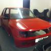
Thijs_Rallye 90 4 Cars Posted November 6, 2024 On 11/2/2024 at 5:03 PM, DC2T said: but i may put the STEPs That would be nice of you! Share this post Link to post Share on other sites
DC2T 54 Posted December 13, 2024 (edited) The Satchell subframe arrived, and i must say is a lovely bit of kit. I missed off the steering rack mounts for now so i could model the engine in place. If i have the drive flange holes and gearebox outlets in line the engine fouls the frame, so ive had to move it up and forward slightly and it looks like it will sit nicely here Edited December 13, 2024 by DC2T Share this post Link to post Share on other sites
DC2T 54 Posted December 17, 2024 It looks as though i have plenty clearance in the driveshaft angles. I still want to model this better. But my positioning appears as if it would work out Share this post Link to post Share on other sites
DC2T 54 Posted December 17, 2024 Will have to be shortened a bit, but still Share this post Link to post Share on other sites
DC2T 54 Posted August 18 (edited) Ok, after a spell away im back in the game. Forgot i had several of these . Saw them one day when in the garage and it just clicked. Slight mod to add a hole and remove unnecessary material and the standard mount can be utilised for the rear of the box. This side of the mount locates off the x section of the satchell subframe and sits at the correct position due to having the underside cut to mount the pipes. Quite elegant if I do say so myself. The support is directly under the bolt, so should give superior support. Once all these mounts are test fit I will do some weight reduction on them, they're a bit chunky as the are. Edited August 18 by DC2T Share this post Link to post Share on other sites
DC2T 54 Posted August 18 (edited) 3d printed out a full scale engine to use for the mock ups. Beautiful isnt she? Edited August 18 by DC2T 3 Share this post Link to post Share on other sites
DC2T 54 Posted August 18 (edited) Edited August 18 by DC2T Share this post Link to post Share on other sites
DC2T 54 Posted August 18 Just scanned the gearbox last night and started printing today. Will have the full mockup done by the weekend to test alignments and clearances. But so far, all looking good. Im not massively happy with the gearbox side mount. But we'll see what it's like when I get it in. Itll be redesigned with laser cutting and bending in mind so should be a lot stronger Share this post Link to post Share on other sites
pugdamo 112 2 Cars Posted August 18 Good to see you back at this, looking forward to seeing the progress. Also I love that 3d printed engine lol Share this post Link to post Share on other sites
DC2T 54 Posted August 21 Thanks man, yeh it's sick isnt it. It works so well for test fitting. Weighs nothing. Ive just ordered some panels for it, and im gonna be doing the fit up of the engine tomorrow. If it goes in alright, ill start machining all the mounts too. Its moving quite quickly now tbh, now there's light at the end of the tunnel it's spurring me on Share this post Link to post Share on other sites
DC2T 54 Posted August 21 Ive just scanned the front grille, im going to make a replaceable central insert with maybe the red H badge from the integra. But ive always loved the full 3 bar grilles from back in the day. Ill 3d print it out when im done Share this post Link to post Share on other sites
DC2T 54 Posted August 22 All done for the bars I think ill add in some sort of venting under the louvres, as i always remember ppl complaining about the big plate blocking air flow Share this post Link to post Share on other sites
DC2T 54 Posted August 23 So last night i got it fit in the bay, slight issues the "stud" off the gearbox broke off so i had to glue the mount to it. Not ideal cause there was movement in it. Going to drill through and bolt them together today if i can find a usable drill. I dint photo it, as i couldnt hold all the bits, but the rear mount didnt look as though it were anywhere close to where it should be, so ill see whats going on there. I was quite shocked at the level of the thing, i know it technically should be as thats how i had set it up in CAD, but i never expect things to actually work out. Either way, progress Share this post Link to post Share on other sites
welshpug 1,737 Posted August 23 that gearbox mounting seems ratther ungainly, a huge amount of levetage going into the bush! would it not be better to remove the original definct cradle and create something akin to the original 205 gearbox mounting bracket, some csk rivnuts in the chassis would hold it nicely, or put crush tubes and through bolts Share this post Link to post Share on other sites
DC2T 54 Posted August 23 1 hour ago, welshpug said: that gearbox mounting seems ratther ungainly, a huge amount of levetage going into the bush! would it not be better to remove the original definct cradle and create something akin to the original 205 gearbox mounting bracket, some csk rivnuts in the chassis would hold it nicely, or put crush tubes and through bolts Most certainly, i dont like it either. I would imagine the rear mount would help quite a bit but cannot say to what degree. I was trying first to design it in a way that would just bolt in, without any modifications to the chassis etc. But i wouldnt sacrifice strength to hit that goal. In the Integra it actually has 5 mounts, 2 on the front aswell and they both lineup with the chassis arm on either side. I hadnt considered rivnuts, but youre right they might be a good solution. Ill draught something up Also figured out the rear mount position, the mounting points are on another piece of the gearbox i havent printed yet, when i measure the rough position from the top hole. It eyeballs pretty close with my calibrated eyecrometers It goes into the 2 holes right of the driveshaft hole And lines up well Also... Share this post Link to post Share on other sites
DC2T 54 Posted August 23 Ive scanned the innovative gearbox mount i have, and it positions very nicely near the chassis arm. It a surprisingly optimum position, almost like it was meant to go there .... Thoughts on this one? I like it more, the angle of the mount does not seem to be ideal, but i dont necessarily think it would make much difference with the others holding. Share this post Link to post Share on other sites
SRDT 253 Posted August 30 Looks like it could go a bit more to the driver side, how much room do you have to change the timing belt with the engine still in the car? Share this post Link to post Share on other sites
DC2T 54 Posted August 31 (edited) The reason it is where it is, is because of the position of the gearbox in relation to the sub-frame. So i dont think i can go further to drivers side without modifying the satchell sub-frame. Which id rather no do if possible I'm printing the last part of the engine now, which is the output shaft area from the gearbox. Should be ready in 4 hours which will allow me to fit the driveshafts in and check the angles while in lock to lock Also, am i right in thinking this is roughly how the steering rack should go? i remember it differently but it wouldn't seem to fit well any other way. I might have to incorporate the rear mount and rack mounting into one piece. Not a big problem, just need to design it. I asked when it was made not to weld in the mounting points as i knew it was going to be in the way but as i could get the CAD model i couldn't design anything then. Looking at this pic though i already have an idea Just bought myself a full steering column, so when that arrives ill attach it all up and see where its wanting to live. Looking at the column though, this does look right. Edited August 31 by DC2T Share this post Link to post Share on other sites
DC2T 54 Posted August 31 (edited) Looks like it should work, scanned the rack i have. Am i right in thinking the only differences in the racks are the lock to lock amount? and not the size/shape of the units? With a 6mm thick tab, we have clearance, Clarence Edited August 31 by DC2T Share this post Link to post Share on other sites
DC2T 54 Posted August 31 Ok, new design done with supporting structure on other side Printing now, will try tomorrow Share this post Link to post Share on other sites
welshpug 1,737 Posted September 1 pas racks would be bulkier around the pinion, and have the collar and stud on the opposite side for the ram but that is mounted on the rear so clear of the mountings. gearbox mount looks a lot better Share this post Link to post Share on other sites
DC2T 54 Posted September 1 Ill be going for a non power steering one. So that sounds good. Cheers, much happier with this one, ive got the rivnuts ready. Just waiting on a tool for inserting and ill make a start. Share this post Link to post Share on other sites