

Introduction:
When you start to "tune" an engine, basically all you are doing is attempting to increase the flow of air into and out of the combustion chambers.
The problem with increasing the airflow is that you will also need to increase the amount of fuel to maintain the correct air/fuel ratio. The reason for this being that air burns hotter then fuel if you start to burn too much air and not enough fuel the combustion chamber will start to develop "hot spots", these being red hot bits of carbon or parts of the spark plug. When this happens the air fuel mix will start to ignite on these spots rather then when the spark plug triggers it, this is very bad and can cause massive amounts of engine damage because if the air/fuel mix is ignited too, early you are literally forcing the piston back down the wrong way. Pistons can be melted because of the higher temperatures created by a lean mix.
Additional Injectors:
The most common ways of increasing the fuelling requires either replacing your injectors with ones capable of a higher flow or adding additional injectors. I will concentrate on the latter in this article. One of the advantages of using additional injectors against replacing the O/E ones is the cost. A full set of higher flow injectors would set you back about £400 new or about £80 second hand and then you would need to think about mapping. A single additional injector would cost you £10- £15 second hand.
The first step is attempting to source the injector you will need. If you look at the specs of the O/E injectors, you can find out approximately how much horse power they can each cope with and see if a 5th injector of the same type will be adequate. You may find that if you are hoping to reach 180+ bhp, another O/E injector might not be good enough and you might need use a higher flow injector. information can be found on injector flow rates and HP values on the internet.
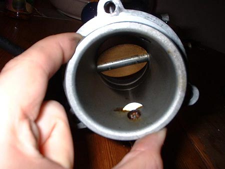
a 205 GTI 8v throttle body machined by Turbo Technics
The next thing you will need to think about when fitting another injector is finding a place to position it. A common place to mount an additional injector is in the throttle body or in the inlet manifold but both will require some degree of machining. I had my throttle body machined by Turbo Technics in Northampton but any good engineering place should be able to do it for you, or if you are feeling brave you could have a go a drilling it yourself.
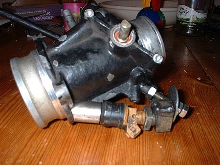
5th injector with a custom fuel hose connection
Hooking the injector up to the rest of the fuel system is not that difficult. You will need to put a T in your fuel hose and run it to you fifth injector, remember to only use high pressure fuel hose and good quality fuel hose clamps for this as the last thing you want to do it spray petrol all over your engine bay. The cheapest way to connect the hose to the 5th injector is just to use some rubber hose and a metal joiner. However, I used a homemade injector connector I made out of an old fuel rail I got from a scrap yard. I just cut it off after the first injector socket and welded a plate over the end. This left me with the connection for the fuel hose as well (see the picture above).
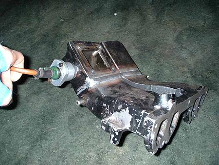
a 205 GTI 8v inlet manifold modified to fit a supercharger and a 5th injector
Injector Controllers:
When you have your injector all plumbed in and you are satisfied that there are no leaks, you will need to think about setting it up. For this you will need some kind of injector controller, I used an MF2 but there are plenty of others around and I am sure they all do more or less the same thing, so hopefully the information I give about tuning the MF2 can be applied to other controllers as well.
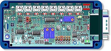
Aquamist MF2 additional injectors controller
All of these controllers will require some form of "map" to tell it how much fuel to inject and when. These maps are created from in the output of 2 or 3 different sensors, hence 2D or 3D mapping.
In the case of an additional injector controller, a 2D map quite simply will inject a set amount of additional fuel according to RPM, you will however need to set-up a throttle switch so you do not over inject when you come of the throttle, this is a very crude way of setting up additional fuelling as air flow can vary with any given engine speed.
A 3D map will inject a set amount of fuel according to RPM and airflow. The RPM signals are picked up from negative pulses from the ignition coil. Air flow is determined by signals from the air sensor (Hot Wire / Flap Type AFM / MAP sensor) or alternatively a throttle position sensor. A TPS determines the airflow by assuming airflow is content at a given RPM throttle position (load site). A flap type AFM works by measuring the airflow using a flap that when displaced by the vacuum of the engine it sends a voltage to the ECU that translates as a precise amount of air entering the engine. The TPS senses the position of the throttle butterfly and sends a corresponding voltage to the ECU. Imagine the ECU as a lookup table with many different load sites that determine how much fuel is injected into the engine. Each of these load sites will be a cross-reference between throttle position, engine speed and airflow, some sensors like engine and air temperature may also effect how much fuel is injected into the engine as a cold engine will require more etc.
A fifth injector controller is simply a scaled down ECU with adjustable amounts of fuel for each load site, the load sites work in the same way as an ECU and can interface with the engines airflow sensors to calculate these sites.
Forced Air Induction:
One of the main reasons for fitting extra injectors is the presence of forced induction e.g. a Turbocharger or a Supercharger. As explained above, when you are increasing the airflow into the engine you will also need to increase fueling to maintain the correct air/fuel ratio. One of the problems inherent in using forced induction with an engine is the increased chance or pre-ignition in the combustion chamber due to a higher density of oxygen in the compressed air. To prevent this, not only do you have to maintain correct air/fuel ratio, but you often have often need to cool the air, lower the compression and retard to ignition as well.
The concept of mapping with a forced induction engine differs slightly because you need to account for the amount positive pressure entering the engine. A simple set-up would be a pressure switch that would trigger injection at a set boost pressure and the amount of fuel injected would be according to RPM and throttle position, this would work fine with superchargers as the boost pressure is directly related to RPM and forms a very linear and predictable graph. Turbo chargers however compress air directly related to the flow of exhaust gasses rather then RPM and so cannot be effectively mapped in this way.
Setting Up:
To set-up a more accurate 3D map you would need an air pressure sensor or MAP (Manifold Absolute Pressure) sensor, these devices work by sending out a voltage according to the amount boost/vacuum present, and you can set an offset on the injector controller and increase fuelling according to this voltage.
You can also use the AFM in conjunction with a pressure switch to form a 3D map because the AFM will send out a similar incremental voltage to a pressure sensor. The problem with using the AFM is that it will not be able to detect a drop off in boost pressure if you are using a dump valve. The purpose of a dump valve is release the pressure backing up when you close the throttle body in order to keep the turbo spinning, this has the effect of fooling the AFM into thinking air is still entering the engine because turbo continues to spin and draw air though the AFM, for this reason a pressure switch is necessary to tell the controller when there is no boost present and to stop injecting in the same way the throttle switch tells the ECU when the throttle is closed.
One thing to note is, if you are using an MF2 to control injection on a 205 GTI, you will need to half the output voltage from the AFM as the MF2 will only accept input of 0-5v. This can be done using resistors.
The conclusion:
Setting any of the above up will require a multi-meter and access to a rolling road.
If you are going to attempt to map the device yourself, you will need to first measure the output voltage of your chosen device at normal atmospheric pressure and set the offset of the controller accordingly. In the case of using the AFM, the offset will need to be set to the point where the standard injectors can no longer supply enough fuel.
Providing your chosen rolling road knows what they are doing, they should be able to accurately map the device correctly by adjusting the injection threshold and RPM load points. Alternately if you are feeling brave you can hook up an air fuel ratio meter and a lambda sensor and give it a go yourself.
I hope this helps you set up a 5th injector / controller.