
Article by Dave Walker / Emerald M3D
Introduction:
Although the example shown here is a Citroen BX Mi16 engine the same principles apply to fitting any throttle body set. I have no intention of covering this job on a bolt-by-bolt basis: you should have sufficient mechanical expertise to remove the standard induction system without my help. If you are not sure, get yourself a Haynes Manual.
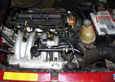
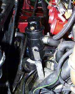
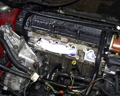
under the bonnet of our BX 16v before the task of installing throttle bodies
One pointer I would give you though is regards the hidden-from-view support strap on the near side (the clutch end) of the engine. This strap runs from the starter motor to the standard throttle body. Remove the strap by unbolting from the starter motor end and keep the strap for re-use.
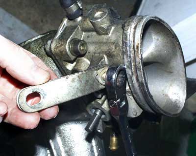
support strap for inlet manifold - fits between starter motor and original throttle body
The Job:
Once all of the standard intake clutter is removed you have a lot more working space.
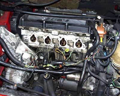
all unused equipment now removed
The first task on this car is to move the dipstick. This swivels to one side but you also have to bend the support strap down to clear the throttle pot once the new bodies are fitted.
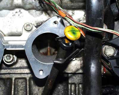
original dipstick position needs to be moved as it
interferes with the new manifold/throttle body
new dipstick position, new inlet manifold and throttle bodies now clear
testing throttle pot position and clearance
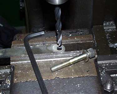
Next, the coil needs a new home. It was previously bolted to the inlet manifold, so I turned it upside down and bolted it to the engine’s lifting bracket. This involved drilling out the coil flange for a larger bolt and penny washer. This was a quick fix to get the car running but it works fine so like many “temporary” fixes it will no doubt sit there indefinitely.
opening out coil mount hole for larger bolt
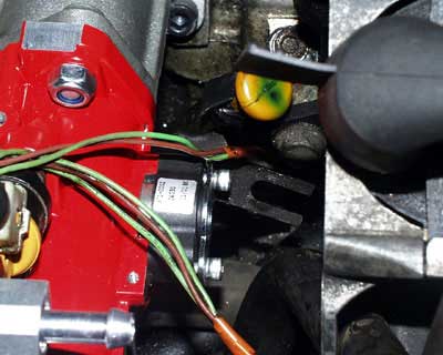
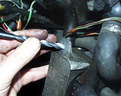
The oil filler trap/pot needs to be moved out of the way. I slackened the clips at the bottom of the hose and twisted it to one side. I then drilled out the old plenum support strap and used this to support the filler trap, retaining it on a temporary basis with cable ties – the same story as the coil bracket.
new oil filler trap position
opening out filler trap bracket so it's location can be changed
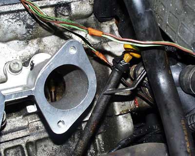
Having cleared the decks you can offer up the new inlet manifold.
inlet manifold to engine mount clearance problem
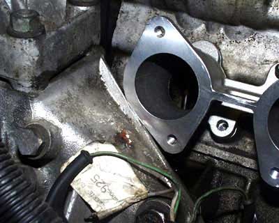
It is an impossibly tight fit at the front of the engine and (although the ports were a remarkably good fit) number four cylinder had a bit of a mismatch.
port to inlet manifold mismatch
You can either ignore it or do as I did and fetch out the die grinder. Put plenty of rag down the inlet ports to keep the swarf at bay and then attack the port.
inlet ports plugged to prevent swarf entering and there is plenty of that about!
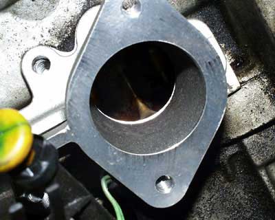
I marked a line with a scriber to work to and it only takes about 30 seconds to get it all matched up. I also improved the clearance around the manifold at the front of the engine.
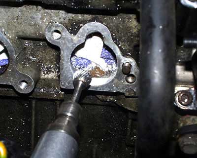
opening out port to match inlet manifold
Note that swarf goes everywhere so a blow out with an airline afterwards helps, as does washing your hair to remove the trendy glitter effect which doesn’t really go with grey hair and advancing years.
Fitting the manifold:
To fit the manifold I used Loctite RTV gasket goo and new cap screws (original bolts/washers won't clear the manifold casting). You may have to modify the length of a few screws or “adjust” the casting to get some screws into the manifold holes.
original bolts replaced with cap screws,
still with no space to use the washers
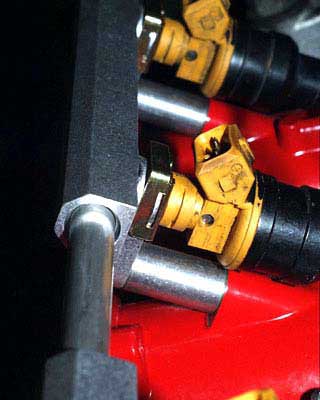
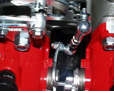
Next offer up the bright red Jenvey bodies. You can use cap screws for the underside flanges but the top ones need studs and nuts because the bolt will not clear the injector’s mounting flange.
studding used in place of bolts, there is no room
to get a bolt passed the linkage & injector mount
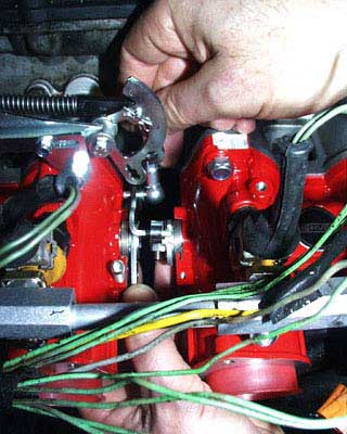
Note that you have to cut off a section of the centre linkage to get both bodies in place. The link-tongue is deliberately left long for engines like the BMW 2002 - which has very wide cylinder spacing.
long link-tongue to allow for different throttle body spacing
Do take the trouble to clean up the cut edge of the link-tongue with a file, as it looks dreadful if left as a sawn edge. Once you have that job out of the way you can bolt up the bodies. These have a sealing ring machined into a groove so there’s no need for gasket sealant. Now offer up the fuel rails.
throttle body to inlet manifold seal
Assembling the fuel rail:
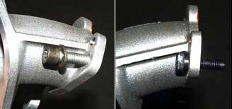
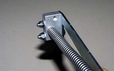
The first thing you find is that the retaining bolts supplied in the kit are not quite long enough if you also use the spring and flat washers supplied.
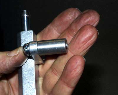
supplied bolts are not long enough if the spring and flat washers are used
You can find longer bolts but if, like me, you are always looking for the easy way out, you will discard the washers and use a dab of Loctite when you later fit them for real.
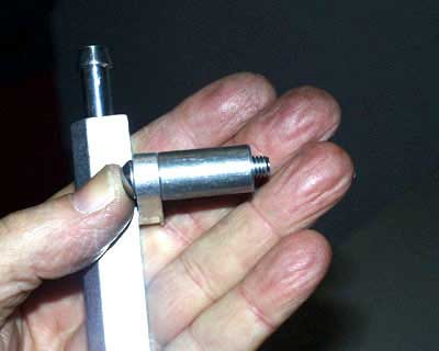
supplied bolt is long enough if the washers are discarded,
use a longer bolt or a little loctite instead
You next need to measure the distance between the rails so that you can cut the link pipe to length. I’ll save you the bother and tell you that you need 77mm of pipe length.
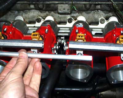
measure the fuel rail link pipe
I cut mine in the lathe you can use a hacksaw and clean up the edges with a file. Put a slight bevel on to aid assembly past the internal sealing ring.
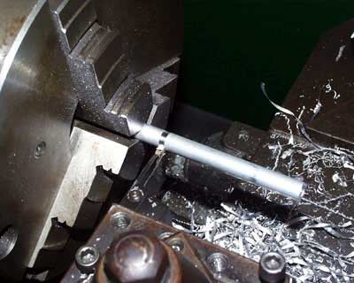
trimming the fuel rail link pipe to length
Refurbishing the injectors:
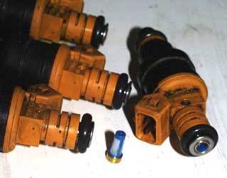
Now turn your attention to the injectors. You can just clean them up externally but ours had done a lot of mileage so I decided to clean them on the ASNU machine – no point in having fancy kit if you don’t use it.
original injectors ready for checking on the ASNU machine
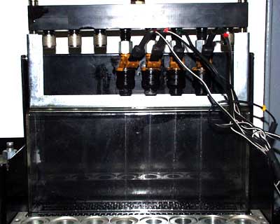
I pulled out the filter baskets and ran the injectors in the ultrasonic cleaning bath.
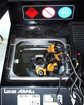
injectors being cleaned in an ultrasonic bath
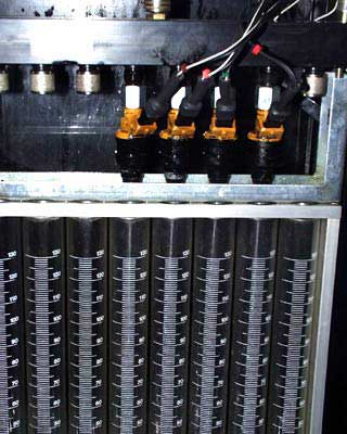
A calibration check then showed three injectors to be matched exactly, with one flowing 12cc/min more. This is caused by dirt trapped internally.
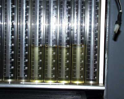
injector four flows 12cc/min more than the other three which are well matched
I ran it through the ultrasonic bath again and it came down to the correct setting.
injectors priming ready for checking after being overhauled
New filters were installed and the refurbished injectors were ready for action.
the injectors filter baskets were all changed
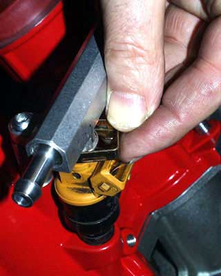
Fitting the injectors:
A spot of silicon lube on the rubber seals aids fitting of the injectors and remember the dab of Loctite on the retaining bolts. New retaining retaining clips are supplied and although they do nothing once the injectors are bolted up I still used them.
new injector to fuel rail clips
fuel rail now fully installed
Now you can tackle the throttle linkage. The Jenvey linkage is expensive at £88 but it is also a superb piece of engineering. The return spring is fail-safe but I have never seen a spring fail. However, there is no such thing as a truly universal anything and the linkage needs some small modification in places.
Assembling the throttle linkage:
First off you have to decide if you are going to mount the linkage above or below the bodies and from which side. The stock cable is very long so I decided that the best run would be obtained by shortening it. Choosing to mount the linkage above requires the above link mounting plate.
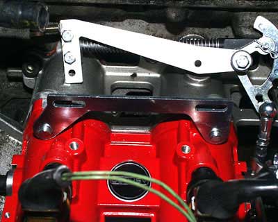
throttle linkage mounting plate
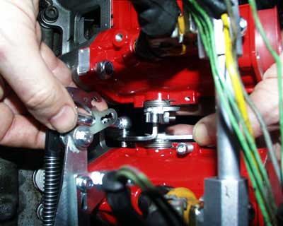
It also makes a difference as to how you assemble the linkage. Picking the left body for mounting means assembling the block as shown in the picture.
throttle linkage block assembled for installation on the left throttle body
The rod has to run parallel with the fixing plate with the cable inside the rod. There is a drawing supplied with the kit but it’s a little confusing.
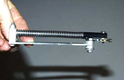
guide rod must run parallel to the fixing plate
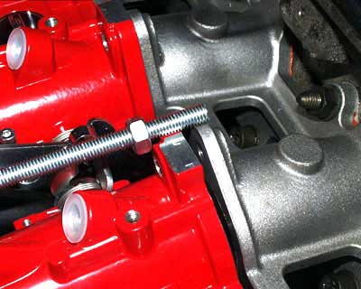
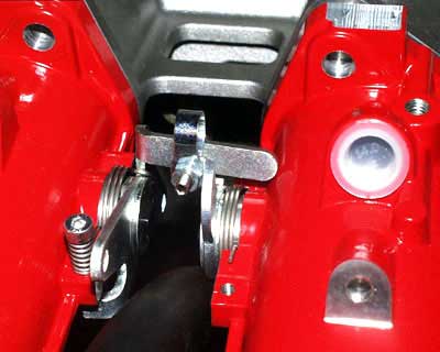
Using the front arm of the lever you get a faster action on the throttle but the ball joint on the drop link hits the body.
the ball joint nut fouls the left hand body limiting throttle movement
This is easily solved by bending the arm with some pliers. I have had to do this on every Jenvey linkage I have fitted so maybe the company will do this job for you once they read this? They did modify the fixing block after my last editorial on their linkage.
the linkage arm has been bent to one side to allow
ball joint to clear the side of the throttle body
Sod’s law being what it is, the throttle cable had failed on our car the week before we opted for fitting the bodies. This meant we already had a new cable fitted. I re-routed the cable and shortened it to suit. Simply pull off the outer sleeve and cut it short with sharp side-cutters. Then feed the outer cable through the linkage and fit the retaining nipple supplied. Use the Allen key at the back so you can fit the screwdriver from the front (anything to make life easier).
TIP: When cutting short the inner cable, use the very inside edge of the side cutters - this will be the sharpest part of the blade because it is almost never used.
You have a choice of link ratio with this kit. I used the one giving the shortest travel at the link as otherwise the throttle pedal reaches maximum throttle about half-way to the carpet.
choice of link arm position determines throttle butterfly travel vs throttle pedal travel
You just know that someone is going to stamp it all the way down and break the cable in the excitement. By using the shortest travel link and adjusting the outer cable you get full pedal travel without problems – just.
Connecting the fuel lines:
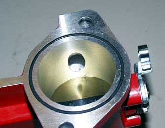
The plumbing comes next. The easy route is to buy an adjustable pressure regulator. If you do then make sure you set the pressure with a gauge, and don’t just trust to luck on the setting as it was when it left the factory. Being unbelievably careful with money I removed the standard regulator and turned up an adapter – after all, I had a lathe handy but not an adjustable regulator.
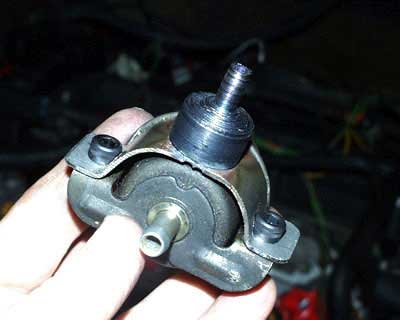
a bracket and adapter allows the original fuel rail mounted regulator
to be used as a remote regulator with push-on pipe fittings
I decided to put the regulator down the front end of the engine where there was more space. This almost led to the old schoolboy error of fitting the pipes on backwards with the pressure feed into the regulator return fitting. You get a lot of fuel pressure this way but none of it reaches the injectors!
I had previously bought some high-pressure fuel hose and also various clips: some Jubilee type, some crimp ones. I had to turn up an adapter to fit the original hose and reduce in diameter to suit my new hose.
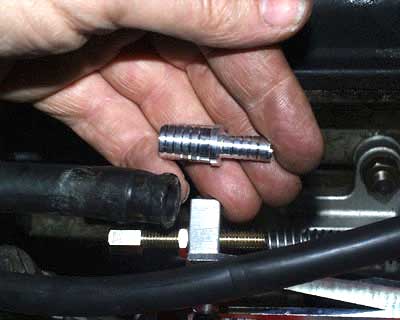
adapter to solve the different fuel pipe size problem
The right size of hose would have been easier but I had a lathe whereas I had only one size of hose. Once all the plumbing was installed I replaced all the wiring and tidied it up with insulation tape and cable ties.
Finishing touches:
The ECU (Emerald M3D) had been on the car for some time (12,000 miles) and we had previously adapted the stock loom to our ECU plug (the plug is supplied free with the ECU on request). All that remained was to tidy up the wiring and fit the air horns.
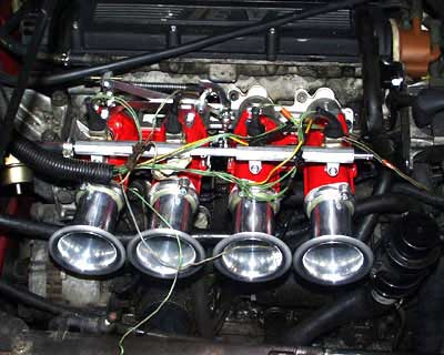
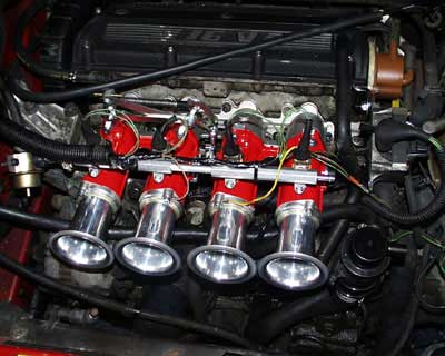
the re-used original injector wiring needs some tidying up

the finished article, awaiting an air box/filter
The conclusion: We have yet to sort out a filter for the bodies after we have checked out the clearance situation. We were lucky in the mapping department because we had previously mapped a standard BX with this engine. The map was installed and the throttle pot aligned and she started first prod.
Call it luck but the “base map” proved to be pretty much spot-on and I couldn’t improve the cold start or idle mixture settings. It drives okay but we will do a full mapping session before we give it full beans on the road. The last car made 185bhp so we wait with bated breath to see if all the effort was worthwhile!
This article is sponsored by:
