

Article by Dave Walker / Emerald M3D
Introduction:
The plan was to take a genuine Turbo Technics 205GTi and upgrade it to an Emerald ECU. This could have been a really easy conversion, but we decided to complicate matters with a few more upgrades!
The Job:
The easy way to convert the TT205 to M3DK would have been to retain the distributor. Pug distributors are not known to be the most reliable of units, but there is a simple fix. Take a VW Golf 1800cc 16v Hall Effect distributor (Bosch unit) and clip on a distributor cap from the Vauxhall Cavalier. This lot bolts to the 205 and then you can retain the original HT leads.
We decided to upgrade to distributorless operation and use the late GTi flywheel and crank sensor. This gives you a 60-2 trigger directly from the flywheel and a factory reliable pick-up sensor. Obviously this means removing the gearbox to fit the flywheel and that's where it all started to get complicated. Armed with the book of lies (aftermarket manual) we started by making up a small section of tube to hold the diff in place once the drive shaft had been removed. In the event this tube fell out several times during the week and it seemed to make no difference at all but we felt the need to follow the book.
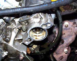
the distributor has been junked
The original TT conversion uses an additional injector in the end of the throttle body to add the necessary extra fuel. The standard management takes care of the fuelling the rest of the time. The fuelling requirement is determined by an air flow meter in the stock setup but the Emerald unit only requires a throttle pot and a Manifold Air Pressure (MAP) sensor. This allowed us to junk a lot of the original clutter from under the bonnet and just pipe cold air to the intake via a suitable cone filter. The extra injector went out the window and we fitted a set of injectors with a larger flow capacity. These were borrowed from a late Mini Cooper (breaker's yard job) but see the injector feature elsewhere on this web site for advice on injector selection. We had a problem in as much as the new injectors were shorter than the originals. The answer was to turn up some stepped spacers with o-ring seals to close the gap. The easier way would have been to find the right length injectors!
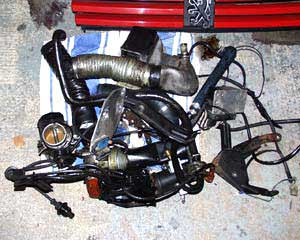
the pile of clutter removed
While doing all this work we found something of a bonus - a fully ported cylinder head!
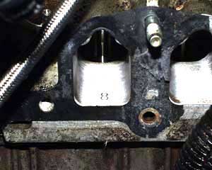
evidence of a ported head
On the wiring front we had little choice but to start pretty much from scratch. The original system is fuel-only with clockwork advance so we rewired the car for the crank sensor, MAP sensor, throttle pot and twin coils plus boost control valve.
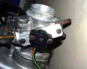
throttle body now fitted with a throttle position sensor
All the pin outs are in the manual along with a generic wiring diagram. To fit the pot we had to make up this adapter bracket.
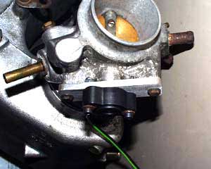
new bracket to hold the throttle position sensor
While we were at it we decided to remove a lot of redundant wiring. Someone had previously fitted an alarm system (wires all the same colour) but the alarm was missing when we bought the car. This was later to prove a real headache but at the time it seemed like a good idea!
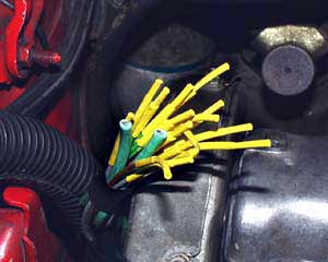
excess wiring from the original installation and the remains of an old alarm system
The TT system used a two-position switch for high and low boost. Low boost is about 6/7psi and high is up to 10/12psi. The manifold design is such that you get very fast throttle response but at the price of high manifold temperatures. We drilled out the outer studs in the head at the exhaust manifold flange and increased the stud size to 12mm as per the original TT upgrade. There had been problems apparently with the manifolds distorting due to excessive thermal load.
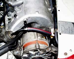
The coil pack we used was from a Ford Zetec engine and we had to adapt the HT leads to suit their connectors. This involved a bit of DIY cutting and shutting but in the event it wasn't too successful. We have since ordered up a custom set of Magnacore 8mm leads.
coil from a Ford Zetec to be used for our distributorless conversion
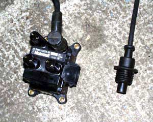
The ECU can control boost pressure but we thought we were lacking the right valve for the waste-gate. For the time being we planned to just set the boost on the operating rod. The right valve was to be added later on. As it turned out we could have retained the original Turbo Technics valve and just plumbed it in differently. As it was we ended up with the Audi TT valve.
boost control valve borrow from an Audi TT
Not part of the master plan was the need for new discs and pads plus drive shaft boots. It was all getting a bit above budget when the service items like engine oil and filter were added on.
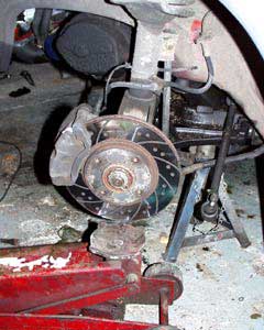
it seemed like a good time to equip
the TT205 with new discs and pads
The M3DK has a small LED on the lid which lights red when the ECU is live. This turns green when the box sees a cranking signal. It's a quick way of telling if the system has power and is seeing engine cranking. All was well, and prior to starting we cranked up the oil pressure with the spark plugs out. The motor burst into life pretty much straight away but we had to call a halt to the warm-up due to a massive oil leak! After much messing about we realised that the new filter was leaking at the seam. I've never seen that before but it was late and we were in time trouble already. A dive into the rubbish bin rescued the old filter and this was cleaned out (as well as we could) and re-fitted.
With the oil leak cured it was a case of mapping the engine on the rolling road. We had taken a power curve before starting, on both high and low boost settings. We were over the moon about the results. We now had better torque and slightly more power on low boost than the engine previously had on high boost! We had yet to fit the control valve to map the boost pressure but it was looking good.
Not so good was the rain outside the workshop and the electric windows that would not wind up! When we removed all the redundant alarm wires we lost the electric window winder controls. It took a lot of finding but eventually the windows closed.
Red Hot:
More of a worry was the turbo temperature. After one power run the turbo was glowing red hot. This isn't unusual but Richard (the owner of the car) was really worried about it. He said that while driving on the road he stopped a couple of times to look under the bonnet and the turbo was glowing red hot in the dark.
We have since fitted a thermocouple into the exhaust to monitor the gas temperature. This reads out via an old tyre temp read-out box which is powered by a PP3 battery. When the battery drains down you get a false (high) reading Richard knows all about this because he lost a couple of years off his life through worry - until he installed a new battery. Now he was seeing maximum temperatures around 850°C which is fine.
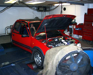
final task was the mapping of the system
When we map for maximum boost we may have to over-fuel the turbo at higher boost pressures to keep the temperature down. It will be interesting to see what sort of mixture ratios we have to run to keep everything together. Fortunately with the full engine management we have the facility to control just about everything and we can now data log to keep a record of what's going on. Richard has already data logged a series of cold starts to fine tune the cold running. The software allows you to start/stop from any recorded function so this was set to water temperature to avoid collecting too much data. It starts anywhere below 20°C and stops at 70°C.
Maximum Boost:
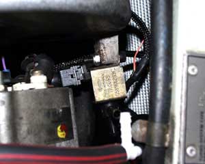
After a couple of weeks running about on low boost the car came back for the plumbing in of the boost control valve. Basically this is a valve we robbed from an Audi TT/Golf GTi 1.8T engine. The valve leaks air from the pipe that goes to the waste gate diaphragm. By bleeding air away from this pipe the boost increases because the waste gate doesn't open when it would have.
boost control valve was plumbed in via a T-piece
connected to the fuel pressure regulator
The biggest advantage of this system is that you can map the boost to stay fairly constant across the rev range. Obviously you can't demand boost where there isn't any available from the turbo - and if the turbo is running out of breath at higher rpm then there's nothing you can do about it.
The conclusion:
Our car originally made a little over 135bhp on low boost and 160bhp on high. Now it is running 160bhp on low setting and 190bhp on high with over 200ft lbs of torque. The problem with the high boost setting is that the inlet temperature is going too high (logged on the M3DK). We are seeing as much as 70°C at high boost. What's now needed is better inter-cooling of the intake charge. The other problem is lack of grip! The car is ridiculous in the dry and lethal in the wet on high boost.
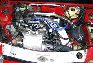
TT engine with Emerald distributorless setup
The turbo overheating isn't the problem we feared it might be but better charge cooling would be the next step to even more power. Always looking for the most cost-effective solution we are planning on making up an intercooler-sprayer. This is nothing more trick than a windscreen washer pump spraying water onto the intercooler radiator. The switching will be controlled by the general purpose PWM output in the ECU on a pressure Vs rpm map which also links to the air temperature. This means that the pump only switches on to spray the intercooler when both boost and air temperature are high.
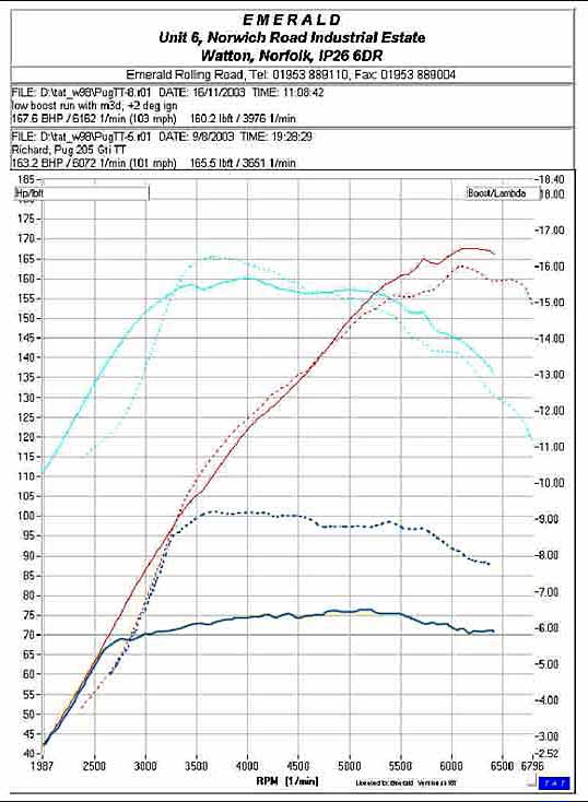
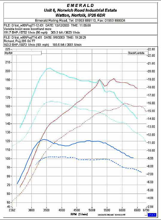
Before and After graphs of power, torque and boost:
GRAPH1 - Original high boost curve (dotted lines) vs new conversion (solid lines). The power/torque curves (red/blue lines) that there is not a huge gain but then notice the difference in the boost curves. The original boost (dotted) peaks at over 9psi whereas the new conversion is peaking just over 6.5psi
GRAPH2 - Original high boost curve (dotted lines) vs new conversion (solid lines). Now running at around 11 psi the TT205 has over 190 bhp and over 200 lbft!
This article is sponsored by:
