

Introduction:
This article describes a complete procedure of fitting an FIA-approved Safety Devices 6-point bolt-in roll cage into the 205.
This Job is not for the faint hearted or people that give in easily. You need time on your hands and to be a competent welder as safety is number 1 with a cage.
Buying the cage:
I chose to fit a roll cage to my road going 205 for a few reasons. Firstly, this cage was going into a 205 1.9 GTI Turbo Technics Conversion and for anyone that has never driven one, they are a hand full and then some with 175bhp as std! Secondly, I have been doing more and more track days with the 205 and have seen 1 car flip which did happen to be 205 also, you will be happy to know it came off very well to say it had no cage fitted.
Right down to business, my 1st decision was what type of cage to order, Safety Devices do various models of cage for the 205. The cage I chose was an FIA approved 6-point bolt-in cage with additional bolt in door bar protection. As my 205 is also road going and has full trim I opted for the removable rear backstays and diagonal as this allows the back seats still to be used when the cage is not required for day to day use.
With my model chosen I then placed the order and Safety Devices gave me a build date for the cage. With the addition of 2 meter lengths of fire proof roll bar padding, the cage came to a grand total of £464.58 inc Vat and Delivery.
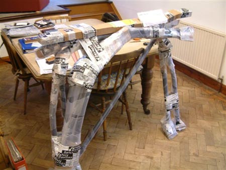
The cage arrived 6 weeks later as 1 big moulded plastic lump as it had all been heat shrink wrapped. I decided to build it in the house to give me an idea of how it all went together and see where my money had gone. It was pretty easy and strait forwards to do. Next was to look at the car and what was requited to fit it all in.
The job:
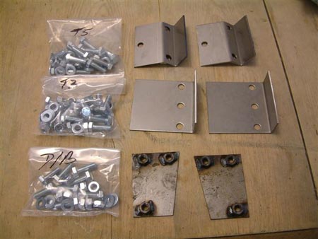
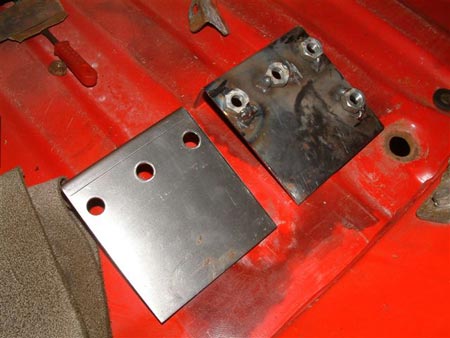
Safety devices sell this cage as a 6-point bolt-in and its not! It should be sold as a 6-point bolt/weld-in cage as I was to find out at great time and labour. The cage comes with big bags of nuts and bolts + load bearing plates, some smooth and some with nuts pre welded on the back. It was my understanding that these plates would go on the underside of the body and sandwich the car shell between the 2 plates. But not so, some of the plates have to be welded to the floor pan on the inside of the car and the captive nuts allow the cage to be bolted to that.
So the first thing to do was to strip the entire interior out of the car, all the seats, the carpets, side trims, grab handles, rear view mirror - basically everything that could get in the way and also catch fire or get damaged due to welding sparks ect. With everything out of the way I could then start to do a dummy run in the car and assemble all the parts of the cage in the car to mark up and see what went where. It became apparent very quickly just how tighter fit the cage was in the car as things were catching and some not even standing up correctly in the car.
With it loosely erected in the car, I could then move it forward and backwards JUST to see where was going to be the best fit/position in the cab.
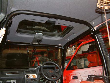
The main problem I found was the sunroof and the sliding cover that covers the glass, with the main hoop fully up at the B post it was crushing the headlining and the sliding cover. Thus this was being rendered useless. I do not use it much except during winter to help keep the heat in so I managed to strike a fine balance between using 2 hands to slide it and the hoop being fully up.
With this done I then marked the 4 foot plates, 2 in the front wells and the 2 at the B posts in the rear with the cage bolts almost tight. I also found it very important to bolt in the door bars as well to make sure the distance between the A and B posts were going to be exact to enable removal of the door bars for every day use, Then I dismantled the whole cage and removed it from the car again.
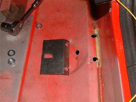
I offered up the plates in the foot wells and decided I was going to do these as a sandwich style and bolt the support plates on the out side of the car and trap the car body between the cage, this option is listed in the fitting instructions. Where the floor pan meets the sills there is a thick bead of sealer I cut this out where the plate was going to sit, so it would be flush to the wall then marked the 3 holes and drilled them out, the same was done on the other side.
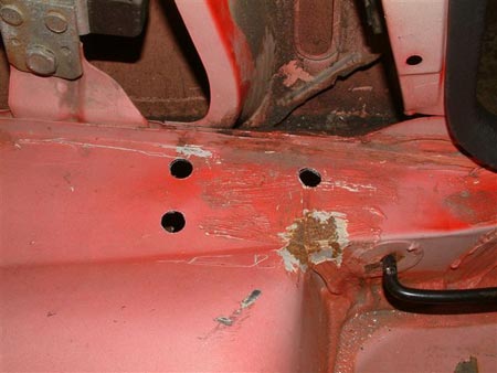
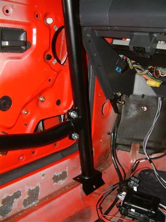
The plates for the main hoop run close to the B post and the foot plates sit on a box section, near the seat belt tensioners for the front seats. The way I initially understood the fitting of these plates was that you did the same as the fronts and marked the holes from the top then offered up the load plates from under the car by means of dropping the fuel tank out to gain access. But to great dismay this was not the case as on removing the fuel tank I found the box section to be 100% sealed all the way round.
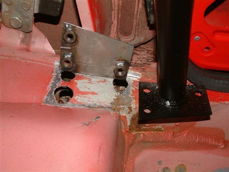
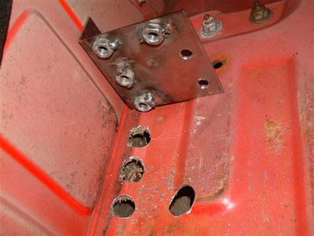
What has to be done is, the plates marked up from the top and the holes drilled then the holes enlarged big enough for the nuts tacked on the back of the plate to be sunk into the floor from the top side. Each nut hole was a 1 off size and took quite some time to get to fit and a lot of metal from the car had to be removed in the process. On looking at these load plates there was a large area of to one side that was untouched so I decided to drill a ½" hole in the plate my self to allow an extra pool weld to be done in the middle of the plate for extra strength. These two plates were made to fit 1 on each side.
This also threw an extra little problem into the equation in the form of adding an extra 2.5mm height to the main hoop on either side and pushing it up even higher into the roof lining. I managed to overcome this problem with the help of a 3LB lump hammer and knocking the floor pan slightly lower before the plates were welded up to drop the overall height.
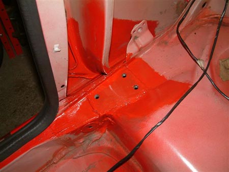
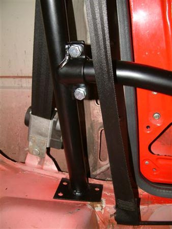
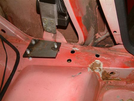
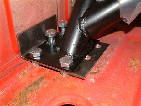
With these two plates ready, they were then tacked in all 4 corners to stop any distortion from the seam heat. Then they were finished off with a seam weld on all 4 sides and finally the extra hole I had made was pool welded up flush to the top.
The cage was then re-assembled back in the car and bolted up tight into position and I finally added the rear diagonal bar which is the removable part and runs into the boot floor pan of the car, with the top bolts in place I was able to mark up the foot plates ready for drilling and welding.
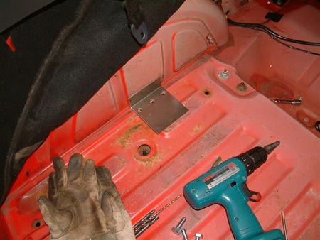
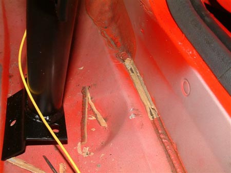
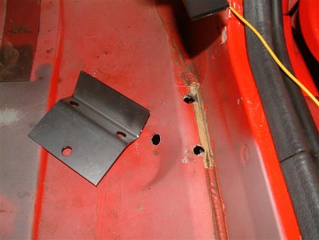
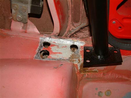
The same sort of method was intended for these foot plates as the B-post BUT Safety Devices idea was to weld the smooth plates into the floor pan then you were to nut and bolt the foot plates into position by means of getting under the car and tightening 8 nuts up 4 of which were directly under the exhaust and the other 4 were under the spare wheel. Remembering that this section was meant to be removable for easy use of the back seats for day to day use, I worked out it was going to take roughly 1½ to 2 hours to remove the rear brace section each time so in the end I decided to adopt the exact same method for these plates as the B-post plates.
This was to take the load plates and tack 4 nuts to the back of each plate then sink the plates into the floor and seam it all up. I also managed to drill 2 extra ½" holes in these plates to allow for pool welding again. It was quite hard to make the nut holes in the floor pan of the boot as the floor was uneven due to ribs in the metal. Also trying to seam all the way round took its time due to some very large gaps, so the large areas had to be built up in strips going over again and again 1 or 2 of the nuts helped bridging the gaps and it was all managed in the end.
With all this done the cage was dismantled and removed again, then all the plates and welds were cleaned up and painted with an etch primer first, then a top coat of hammerite to seal them. I also took the opportunity to treat a few spots of surface rust that had started to appear.
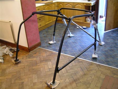
Finally I was ready for the final build of the cage, so everything was put back in loose then gradually I went round in a logical progression and tightened up all the nuts and bolts tighter and tighter until everything was done. The cage was in !
The conclusion:
A few things I found out was that I could not get the rear view mirror back on due to the bar running across the screen and also the glove box door did not open more than 3 cm. The mirror was solved with a trip to Auto Windscreens where the guys there bonded me on a new mounting point for the mirror lower down the screen and the glove box was solved by cutting a thin strip off the NS of the door to allow it to open fully. I glued the cut off strip back to the dash board so when closed you can not see the missing part.
All the interior carpets and seats were put back in and ready to roll. The fist drive was fantastic, the difference the cage had made to the handling was amazing, the shell and chassis is SO stiff now and the turn in feels twice as sharp again, cornering on 3 wheels is quiet common as is picking up a back wheel at speed on a corner. You notice just how stiff it is when you go to change a wheel as when you jack 1 wheel up you end up lifting 2 as its just so stiff now.
After 3 months of driving with it now I am still happy with it and do feel very safe driving around with it in, the only thing that bugs me now is the amount of squeaking the cage does rubbing on the head lining on a bumpy road, on a smooth road its fine. Not the end of the world though and a small price for saving your life.